

In order to guarantee an instantaneous trip on 100% of the line while maintaining the same level of security, communications-based logic is often used. A large number of variants have been developed, from the permissive underreaching transfer trip (PUTT) to the permissive overreaching transfer trip (POTT), all of which have their justification depending on their use. Before commissioning distance protection with communication, it is absolutely necessary to know, understand, and test the method used in detail. Due to the brevity of this article, the relationships here are described with reference to distance protection with permissive overreaching transfer tripping [1]. POTT is, in practice, the most appropriate protection method for weak infeeds, short lines, multi-terminal or tapped lines, and strong intermediate infeeds. Checking this function on different system conditions is therefore of particular interest and importance.
Method of operation of permissive overreach tripping
In POTT schemes, receipt of a transfer trip signal releases an overreaching distance zone, Z1B. In the event of a fault on a line fed from both ends, both protection relays detect the fault in the forward direction and send each other a release.
In the case of very short lines, where the actual Zone 1 value is less than the minimum value possible for the protection relay, receipt of a tranfer trip is mandatory for the trip. Otherwise the "Trip" can be sent from Zone 1 without a release (Figure 1).
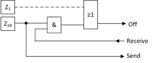
Figure 1. Distance protection with permissive overreach transfer tripping
Weak infeed and echo function
One particular feature of POTT schemes is the ability to achieve 100% protection instantaneously, even during weak infeed conditions. If a fault occurs near the weak infeed, the fault current can be less than the distance protection pickup. Without special logic, the protection relay at the weak infeed would not send a transfer trip and only the remote protection relay would trip in Zone 2 time. A special logic in the relevant protection relay detects a weak infeed from the undervoltage occurring due to the fault, or from the absence of a pickup from the reverse zone while at the same time receiving a transfer trip. In this case, the local circuit breaker (CB) is tripped and the transfer trip signal from the remote end with a strong infeed is sent back like an echo.
A similar condition occurs if the protection relay receives a transfer trip while the local CB is already open. In this case the fault must be on the protected line. If the CB is in open state, the local relay echoes back a transfer trip and the remote protection relay can respond instantaneously.
Reverse current monitoring
Due to the overreaching release logic, special precautions must be taken when using parallel lines. This becomes clear when considering the precise chronological sequence of events during a local fault in a parallel line (Figure 2 A).
Relay B1 measures the fault in the extended zone and sends the transfer trip signal. Protection relay A1 measures the fault in the reverse direction which prevents an instantaneous trip. At the same time, the protection devices A2 and B2 of the faulty parallel line detect the fault and both trip instantaneously. We now assume that circuit breaker A2 opens shortly before circuit breaker B2, due to the time tolerances, which results in a current reversal for relays A1 and B1 (Figure 2 B).
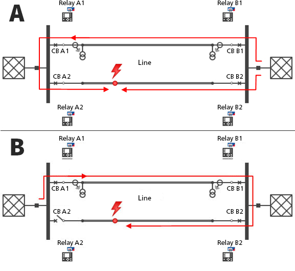
Figure 2. Current flow in the event of a fault (A) and reverse current after circuit breaker Off (B)
Relay A1 now detects the fault in the forwards direction in its extended zone. At the same time, relay B1 detects the fault in the reverse direction and consequently revokes its transfer trip signal. When this happens, relay A1 detects the forwards direction earlier than the drop of the release from B1. This period is shown in red in Figure 3. According to the POTT logic, relay A1 should now trip immediately. This unselective tripping is prevented by what is known as current reversal blocking. This logic blocks POTT for a defined period after the detection of a current reversal.
Testing
A wide variety of test methods exist for commissioning POTT schemes which differ in their testing depth (Table 1).
When setting up the test case, it is advisable to always simulate a fault scenario as realistically as possible, regardless of the test method. This includes simulating the CB auxiliary contacts, for example. The pickups of the individual elements in the logic should be included in the log for evaluation if possible.
| Function | Fault scenario | Evaluation criteria |
| Overreach | Stable power flow | No pickup and trip |
| Communication fault | Fault in Z1 and Z2 | Trip corresponding to time grading |
| Backup protection | Reverse and forwards fault in the subsequent line | Trip corresponding to time grading |
| 100% instantaneous | Fault along the line before and after Z1 boundary | 100% instantaneous trip |
| Reverse current monitoring | Fault in parallel line, followed by time delayed CB "trip" on the parallel line | No trip, read off blocking and pickup |
| Echo function | Local fault on the line with an open local CB | Release sent from the local relay and instantaneous trip of the remote relay |
| Weak infeed signal | Local fault at the weak infeed | Instantaneous trip despite no pickup of the extended zone at the weak end |
| Weak infeed overreach | Local fault in reverse direction | Trip corresponding to grading |
Table 1. The test methods for commissioning POTT differ in their testing depth.
Single-ended testing
Since the release signal is binary information that can easily be simulated by a test unit, single-ended testing of a relay is frequently employed. A prefault state is output for the main function, followed by a fault in Z1B while simultaneously simulating a tranfer trip signal. The instantaneous trip and the sending of the transfer trip to the remote protection relay are evaluated. Good test solutions allow the fault situation in the impedance plane to be defined, including the representation of the distance protection polygons and tolerances. The test sequence described above can then be set up relatively easily. At the same time, this allows the reach of the extended zone and the logic circuit to be verified.
System-based testing
The following are important factors influencing the subsequent operation of the protection system, but which are disregarded by single-ended testing are:
- Communications delay (timing)
- Correct alignment of the relay settings to each other
- Real infeed conditions
A system-based test is advisable in order to draw a conclusion as to whether the protection system, consisting of two or more relays; their settings; and the communication system adequately protects the system under test. An ideal system-based test takes place at all ends (end-to-end), and is time-synchronized.
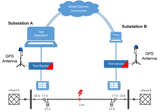
The signals are calculated with the aid of a simulation of the grid section to be protected. Every fault scenario can be implemented directly using fault and CB events. In this way, a simulation of the grid allows the protection system to be tested under real infeed conditions. For example, whether or not the "weak infeed" threshold value has been correctly selected can be tested. This additional test quality feature would also be present if the protection test was single-ended with grid system simulation. However, simultaneously testing both ends also takes into account the operation of communication systems, the influence of delay, and the tuning of the protection relays to each other. Software solutions, which combine a transient grid simulation with simultaneous activation even of distributed test sets already exist to carry out such a system-based test. This considerably reduces the time taken both for setting up and for executing the test. Furthermore, test solutions of this kind can include time delayed "trip" commands for the protection relays in the simulation, which not only reveals timing errors, but also checks logic functions such as the AR as well.
Summary
Commissioning a POTT method often requires more than just testing the instantaneous trip over 100% of the line. Single-end tests with stationary sequences are simple and proven test methods. The complexity when designing a POTT scheme should not be denied, however. A system-based test here offers a simple but effective way of finding any faults.
Literature
[1] Ziegler, G.: Digitaler Distanzschutz [Digital distance protection]. Verlag Siemens, 2nd edition, 2008
Author
Dipl.-Ing. (FH) Christopher Pritchard is Head of Product Management at OMICRON electronics and in particular responsible for system-based testing solutions.