
Many people assume the Smart Grid is a revolutionary change to the operation of the electric grid. In reality, it is an incremental step in the long evolution of adding automation to the electric grid. This general overview presents a history of Electric Utility Operational Control Systems. It spans from the early adaptation to the current era of the Smart Grid. The discussion is presented in two sections: Monitoring-Control Systems and Communication Protocols. A final section integrates these two technologies into the Smart Grid and includes some lessons learned from early implementations. This brief review will not include the automation applied by protection systems and devices.
Operational Automation Systems
There are three generic parts to the operational automation system: The Master Station (central/host location), the Remote Interface Devices – commonly referred to as Remote Terminal Units (RTUs) – and the Communications System. Each is summarized in the following sections.
Master Stations
Some of the earliest Supervisory Control and Data Acquisition (SCADA) systems were installed in the 1920s. At the time, some high voltage substations adjacent to power plants (aka generating stations) could be monitored and controlled from the power plant’s control room. This eliminated the need to staff the substations 24/7 even if the substations were some distance from the power plant control room. These systems consisted of two control and monitoring boards, one in the substation and one in the power plant. Eventually the power plant substation board was reduced to a single panel that could be multiplexed to each of the substation control panels. Power plant governor control – used to change the output of a generator – was essentially a manual operation based on instructions from the System Control Center.
In the 1930s, individual utilities started interconnecting to interchange electricity to reduce operating costs. With this came the need to control generation much more closely, so analog computers were developed to monitor and control generator output, tie-line power flows and frequency.
By the 1950s the analog computers were enhanced to schedule generation to each generator to provide the lowest cost of generation. These functions were called Economic Dispatch (ED) and Automatic Generation Control (AGC), and the systems were labeled Energy Management Systems (EMS). The EMS functions were supported by off-line manual calculations to determine which company could produce the next block of energy at the lowest cost. Negotiations were then conducted between the utilities to set the tie-line power flow schedules.
In the late 1960s, digital computers and software were developed to replace the analog EMS systems. Software applications were developed to include the off-line analysis functions along with transmission system analysis models. Vendors modified the computer supplier’s operating system to meet their design and each set of application software was usually unique for each customer. Thus, when the computers needed to be upgraded or more functions were required the entire Master System had to be replaced. This trend continued into the 1980s and 1990s until open standard operating systems were developed that supported real-time applications.
Some utilities worked with vendors to develop and deploy hierarchical control systems. The lower level systems monitored and controlled portions of the transmission and distribution grids. This reduced the EMS database size and the amount of information communicated to the EMS system.
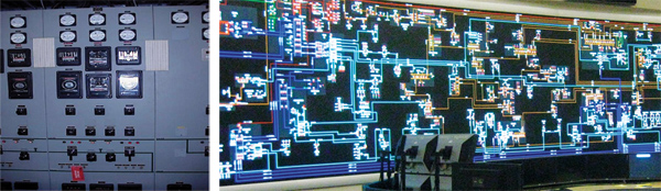
Control Systems: Then... and now
More recently, some utilities have deployed distributed control systems with area transmission and distribution control centers. Other utilities have installed regional DMS (Distribution Management Systems) which communicate with distribution substations as well as with feeder devices (i.e., reclosers, capacitor bank controllers, sectionalizers and feeder voltage monitors). Today, communications to feeder devices is usually wireless. These systems provide closer contol of feeder voltage profiles and faster determination of faulted feeder sections to improve service restoration times.
Some utilities are also deploying master stations into T&D substations. These substation master stations may operate independently for some automation functions and as slave devices for other functions, with the ultimate control being assigned to the network operations center.
With the move to Open Market operations, there have been shifts in the locations where various operation and monitoring functions are performed. The generation control functions, in many cases, have been moved to Independent System Operators (ISOs). The transmission analysis operation functions have been transferred to ISOs or Regional Transmission System Operators (RTOs). However, some utilities still operate in the traditional manner with integrated generation, transmission and distribution control systems.
Remote Terminal Units (RTUs)
In the early application of monitoring and control systems, the interface between the power system and the control system was in a remote location. This interface was designated a Remote Terminal Unit – or RTU. An RTU consisted of a cabinet or panel of terminals for the instrumentation and control wires, which connected it to the power system. The position of the power system switches and circuit breakers were monitored by auxiliary relays. When the relay was closed, the power system switch was closed and a current was present resulting in a binary “1” signal. When the relay and the switch were open the binary count was a “0”. Analog values were obtained from potential transformers and current transformers connected to the power system buses and circuits.
The transformer output was 120 Volts AC and nominal 5 Amperes AC; these values were converted by transducers to +/- 1 milliampere DC. The RTU had analog devices to convert the analog values into binary values (usually 8 to 12 bits).
Thus, the digital and analog input values from the power system could be sent as a series of binary values to the master station for display and analysis purposes. The auxiliary relays in the RTU used for controlling power system devices were addressable so the operator could select the address for a specific power system device and function, (open or close) and send the command to the RTU.
The RTU remained basically the same until the mid-1970s when rugged microprocessors that could withstand the substation environment became available. The application of microprocessors reduced the hardware complexity of the RTU, but the interface wiring remained unchanged, or even increased as the external milliamp transducers were replaced by internal analog to digital converters. The use of these analog-to digital (A/D) converters required that the AC secondary amperes and voltages be brought to the RTU.
The use of microprocessors provided the opportunity to greatly increase the capabilities of the RTU. These capabilities included time keeping, more complex and powerful protocols, individual point numbering, local logging and time tagging of events, higher communication speeds, multiple communication ports and numerous other functions. But the complex and costly interface wiring continued to exist and kept costs relatively high.
In the 1980s, microprocessors began to be applied to protective relays, meters, various controllers and other devices, which usually were equipped with a communications port. As these more powerful devices were deployed, the utilities and system vendors both realized the substation design and complexity could be greatly simplified by interfacing these devices directly into the RTU. Thus, a new era of opportunity began to unfold. It was also a time of confusion and frustration (as will be discussed in the protocol section). As the application of these devices grew, the IEEE Power and Energy Society (PES) Substations Committee determined that a need existed for a unique name to identify them. It was at that point that the term Intelligent Electronic Device (IED) was coined and defined. Soon, almost any device with a microprocessor and a communications port was deemed an IED.
As the application of IEDs spread to most new substations as well as many updated substations, they quickly became the preferred interface between the power system and the RTU. The application of these devices greatly reduced the magnitude and complexity of the control and instrumentation wiring. In the 1990s, utilities began installing IEDs on their distribution feeders with some communicating to the substation RTU while others communicated directly to the network operations center. In both cases, this extended the reach of their control systems down to the distribution feeder level.
Currently there are tens of thousands, if not hundreds of thousands, of these feeder IEDs in operation that are regularly polled by the SCADA master for updated analog and status data. While these remote IEDs provide monitoring and control capabilities to the system operator, there is little or no automation. Adding intelligence and automation to the distribution feeders is a vital next step leading to the Smart Grid.
Communications Systems
Early utility monitoring and control systems were structured around telephone technology and used leased telephone lines operating at 300 bits/second. Leased phone lines are still the most common communications system element. Many are still operating at 1200 bits/second, but some have been upgraded to 4800 bits/second and a few to 9600 bits/second. Several utilities have even installed private telephone systems with high-speed switching and automatic fault recovery capabilities.
Early on, utilities faced the problem of communicating to very remote hydroelectric power plants, and installed power-line carrier systems between high voltage substations to solve the problem. These systems carried both voice and data, which solved the problem as long as there was a direct link between the two substations. Most of these systems have probably been replaced with microwave. Utilities with large geographic areas have private microwave systems to handle large volumes of information over long distance communication links.
A few utilities have implemented satellite communications for sparsely populated large geographic areas. Fiber optic cable is being used both within substations and as Wide Area Networks (WANs). With the recent concerns about security this is becoming a more attractive and cost effective solution.
Starting in the 1980s, licensed 900 Megahertz point-to-multipoint radio systems became very popular, especially for small substations. These systems provided a substantial cost savings over leased phone lines and were under the complete control of the utility company.
In the 1990s, unlicensed 900 Megahertz mesh radio systems were installed and added to the communications network mix. The first (skeptical) reaction was that these radio systems provided undetermined communication response times and were not suitable for monitoring and control. However, with proper designs and management, these systems have subsequently been proven to meet most requirements.
About the only thing that is certain about utility communications systems is that they usually have a mix of everything. The trend is to add higher speeds with more throughput capacity, but even many large utilities are still operating with 1200 bits/second leased lines.
Protocols
The protocol is the glue that holds everything together. If you have tried to communicate using American English in England or Mexican Spanish in Spain, you understand the potential for problems. The electric utility industry has gone through many phases with protocols for control systems.
In the beginning, there were only a few companies that made hardware-based systems, and practically no one considered interoperability. As digital systems came into play there were more vendors, many of which stayed in business for only a short time, causing concern about interoperability to increase. Also, there was a need to make the protocols more robust and more secure.
The major system suppliers solved part of the problem by documenting their protocol and permitting customers to share it with RTU suppliers. In the 1980s, there were perhaps six or eight shared protocols and another four or five proprietary protocols along with a few “utility-unique” protocols.
When IEDs began to be marketed, the number of protocols exploded like a mushroom cloud. Each new vendor invented a protocol for their device; some even invented a new protocol for each new model. System vendors and utilities were going crazy trying to integrate these IEDs into their control systems. One RTU vendor listed 100 protocols the company had implemented. In the late 1980s, the IEEE PES Substations Committee formed a Working Group (WG) to investigate this problem and to determine a reasonable solution.
The WG developed a list of requirements that a protocol should satisfy to meet the needs of the industry. Information was collected from around the world on 120 potential protocols, which were then screened against the list of requirements. Only about six or seven passed the screening. The WG held a ballot and two were selected: Distributed Network Protocol version 3 (DNP/3) and IEC 60870-5-101. The proposed selection of these two protocols was balloted by the IEEE, and in 1997 IEEE Standard 1379 “Trial Use Recommended Practice for Communication between RTUs and IEDs” was adopted and published.
IEEE 1379 was reaffirmed as a Recommended Practice two years later. It has since been reaffirmed (in 2006). DNP3 is now the most widely deployed and specified protocol in North America, not only for substation use, but also for substation to master station communications. In parallel with this activity, the ownership and maintenance of the DNP3 protocol has been under the control of the DNP Users Group, an open membership not-for-profit corporation since 1996.
The enhancements recommended for the protocol by the Technical Committee and approved by the membership have led to its wide scale acceptance and to enhanced functions. Cyber security features developed by the IEC, Technical Committee 57 (TC57) Working Group IEC 62351-5 have been added to the DNP3 protocol and are presently being tested for performance.
There are two other IEC activates that are sometimes mentioned in relationship to the Smart Grid: IEC 61850 Substation Communication protocol and the Common Information Model (CIM) IEC 61968 and 61970 models. The CIM models should be considered for use by all utilities, since they define the basic elements of the grid and their interconnection and perhaps efficiently to the GIS system. However, it will be extremely important to have a digital database system that can provide data to the Smart Grid control system.
The IEC 61850 protocol includes a number of features that should be considered for any control system – the object definitions and concepts, the use of XML files for defining IED and master station databases and the naming conventions – to list a few. IEC 61850 also includes many functions and features that are related to substation protection systems that may limit its suitability for remote to master communication. It should be noted, however, that some North American utilities are using DNP3, Modbus and IEC 61850 GOOSE (Generic Object Oriented Substation Event) messages on the same substation LAN. This might be called using the best of three worlds.
Lessons Learned
Automation has been applied to distribution system feeders for a long time, especially as related to protection and the restoration of some parts of the feeder. The question now is how can more intelligence be added to get more customers back in service sooner? Some small-scale deployments using rule-based artificial intelligence engines have been very successful. However, there were some learning points along the way…
- In addition to monitoring the power grid, the communication network must also be monitored.
- Power system devices must be properly maintained to ensure they are in operational condition.
- All devices with battery backup systems must be automatically tested to ensure the battery’s capability to support the device.
System operators must be included in the design of the automation logic so they can…
- Understand how it works and when it will work,
- Understand it is not a replacement for them, but a support tool,
- Understand they have control over the logic; not visa versa.
In summary, the Smart Grid era is not a destination but rather a point of departure for the energy automation field. The Smart Grid will add another layer of automation between the protection system and the System Operator, doing the simple rule based things and leaving the complex problems to the Operator. Professionals serving this field will continue to adapt and invent to meet the challenges of ever changing demands of users. The Smart Grid integrates the components of past developments. However, those components are not an orderly unit.
In reality, the components integrated into the Smart Grid are as varied and as diverse as the history of energy automation. The future promises opportunities to refine and to extend the efficiency and the effectiveness of present – and yet to be defined – components.
Based upon the past ingenuity and determination of those developing the energy automation systems, there is no doubt these opportunities will be met with a wealth of new ideas and new products.
It is critical to keep in mind that the Smart Grid applications will, in all probability, be additions to – not replacements of – existing facilities. The investment in current control systems is huge, and it is performing its intended functions. Failure to integrate Smart Grid to the existing infrastructure (i.e., rather than trying a complete replacement or overlay) is probably doomed to be an expensive failure.
Acknowledgements
The author would like to thank the following individuals who contributed their ideas and editing expertise to this article:
- William Ackerman, Consultant, Life Senior Member IEEE
- J.W. Evans, Consultant, St. Claire Group, Senior Member IEEE
- John T. Tengdin, OPUS Consulting Group, Life Fellow IEEE
- Dr. Elizabeth Vernon, Consultant
About the Author
H. Lee Smith is an executive consultant and a Life Senior Member of the Institute of Electrical and Electronics Engineers. His assignments have been in both line and staff positions. Throughout his long and accomplished career, Lee has provided product and/or service support to the electric utility industry for vendors from product application engineering support to management and has also held several executive level positions. His focus has been on real-time information processing and control systems for the last 30 years. He has authored more than 100 technical papers and articles, including a chapter in the IEEE Tutorial on Supervisory Control and Data Acquisition (SCADA) systems. Lee holds a BSEE from California State Polytechnic University (San Luis Obispo, CA) as well as a MSEE from the University of Pittsburgh (Pittsburgh PA). He can be reached at hleesmith@ieee.org.