Industrial electrical equipment is often affected by power supply disturbances, most notably voltage sags. Numerous Electric Power Research Institute (EPRI) studies have found that common, general purpose AC relays often contribute to these electrical equipment shutdowns. Typically referred to as an “ice cube” relay due its clear plastic cover that resembles a square ice cube, these AC-powered relays may be susceptible to many voltage sags that do not affect other elements of a control system. Therefore, they present an “Achilles heel” that may cause an entire machine, processing line, or entire factory to shut down during minor voltage sags. This article discusses the basics of the common AC ice cube relay and documents the power quality issues related to these devices. It also presents EPRI’s call for action to improve these devices in order to lower the worldwide cost of shutdowns caused by power quality problems.

Mark Stephens, PE
Senior Project Manager

Alden E. Wright, PE, CEM
Project Engineer/Scientist
Introduction
Control relays are essential electromechanical devices that activate one or more switches when their coils are energized. In the early days of industrial control, these devices were the primary component used in automation schemes.
Today, however, modern control systems often employ programmable logic controller (PLC)-based control systems to perform much of the logic-related work formerly done by the individual control relays. However, these simple elements are still heavily used in pilot relay applications in many motor-control circuits or when permissives or interlocks are needed between two elements, such as PLC and motor-control center, variable-frequency drive, or another separate machine or control system. Furthermore, control relays are heavily used in safety-related circuits where hardwired controls and interlocks are considered the best option.
Among the many types of control relays available, one of the most common types known as the ice cube is shown in Figure 1.
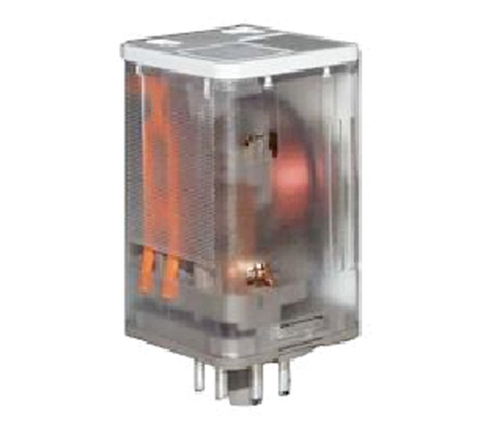
Figure 1: Typical AC
Ice Cube Style Relay
The relays and contacts of these units are normally housed in clear plastic, which has the appearance of an ice cube. Ice cube relays with DC coils are generally resistant to common power quality problems as long as their corresponding DC power supplies are robust. However, ice cube relays with AC coils have shown themselves to be extremely sensitive to common power quality problems. With an average dropout at or near 70 percent of nominal for a cycle or less, these devices can lead to as many as 13 equipment shutdowns per year in a distribution-fed commercial or industrial facility. Example ranges of tolerance for these control relays have been documented in IEEE 1346 and are shown in Figure 2.
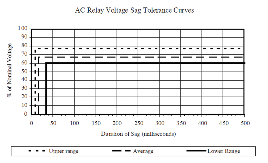
Figure 2: Example of the Range of Control Relay Sag Tolerances from IEEE 1346
EPRI has conducted detailed testing on AC ice cube relays as well. Those tests reveal the susceptibility of these relays to extremely short-duration voltage sags, even dropping out for events that are as short as ¼ cycle (4 milliseconds) to 1 cycle (16.67 milliseconds) in duration.
Because most fault events on the utility system cannot be cleared in less than 3 or 4 cycles, the relays are very likely to be effected by voltage sags. Figure 3 shows composite test results of four off-the-shelf AC ice cube relays. The average response reveals that these relays are susceptible to minor voltage sags regardless of whether or not the sag begins at zero degrees at the voltage waveform or at the apogee of the voltage at 90 degrees.
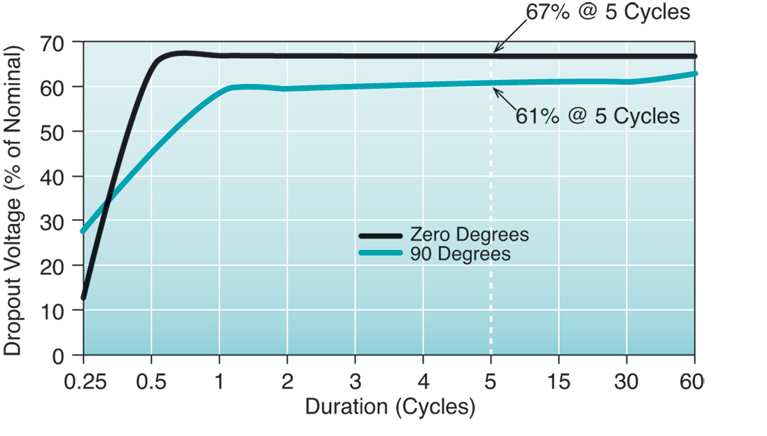
Figure 3: Composite Low-Voltage Tolerance
of AC Ice Cube Relays (from EPRI Tests)
As a result of EPRI’s previous system compatibility research, common industrial control components such as PLCs, drives, power supplies, and motor starters are now available that are compliant with industry power quality standards. Hundreds of off-the-shelf control components may be purchased that can survive voltage sags as low as the 50 percent of nominal and meet industry standards such as SEMI F47. The requirements of this standard are shown in Table 1 and Figure 4.
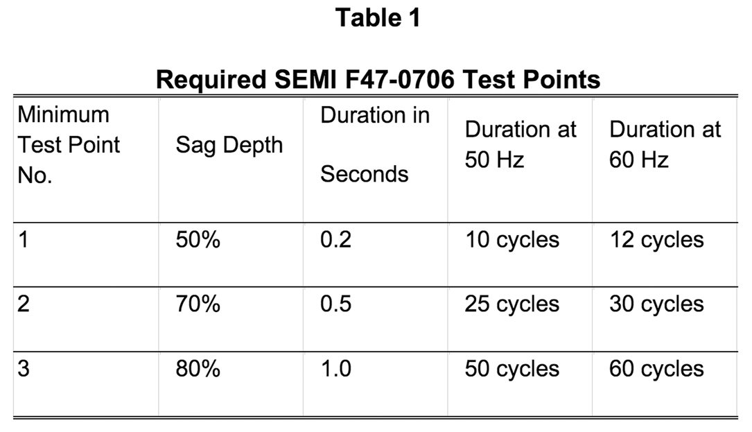
Table 1: Required SEMI F47-0706 Test Points
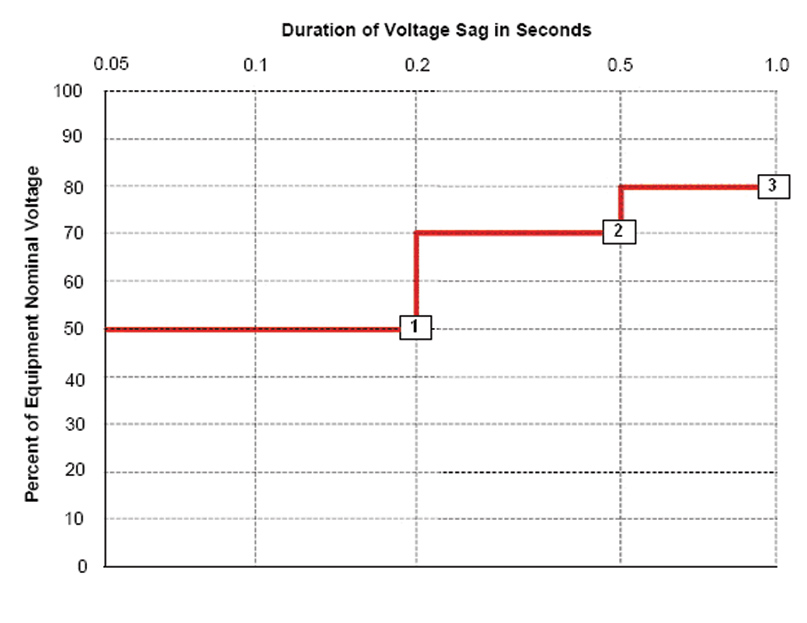
Figure 4: With the Exception of the AC Ice Cube Relay,
Many Components Are Now Compliant with the
SEMI F47-0706 Standard
Other standards, such as IEC 61000-4-11 and IEC 61000-4-34, call for categories of industrial voltage-sag tolerance down to 40 percent of nominal.
Unfortunately, there are no known AC ice cube relays on the market that are immune to voltage sags. While other control components have already made significant leaps in their ability to ride through common voltage sags, AC ice cube relays have not. Because of this limitation, significant power quality vulnerabilities continue to exist in modern machine designs where these AC relays find frequent application. Through power quality audits conducted in facilities worldwide, EPRI routinely finds that the reason for power quality-induced process shutdowns at a great many of these facilities is the simple AC ice cube relay. In fact, some plants may employ hundreds of these relays throughout their control schemes.
Typical General-Purpose AC Relay Design
A side view of a general-purpose relay, seen below in Figure 5, shows the relay to consist of an inductive coil forming an electromagnet, a frame allowing one or more pieces to pivot, and electrical contacts. Figure 6 illustrates the mechanics of the relay, where Figure 6a shows the normally closed (NC) state with the spring’s tension holding the contacts closed, while Figure 6b shows the coil acting to pull in the pivoting mechanism to switch the circuit. An electrical input activates the coil. (DC coils tend to be much more robust with regard to power quality issues than AC coils.)
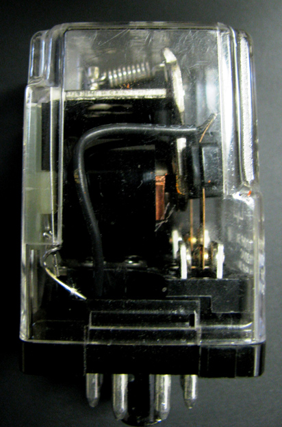
Figure 5: General-Purpose AC Ice Cube
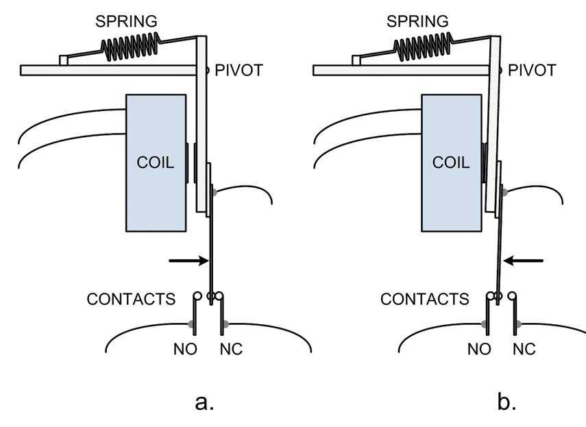
Figure 6: Mechanics of Normally Closed Relay
Typical specifications for general relays may be found in Table 2.
.jpg)
Table 2: Typical AC Ice Cube Relay Specifications
The data in the above table points out that the relays may activate or deactivate in one to two cycles of the power (one cycle is 16.67 milliseconds). While the relays above may operate successfully for around 80% to 85% of nominal voltage, a wide band of ambiguous operation exists between the minimum operating voltage and the definite drop-out voltage given. As the voltage-sag test data indicates, the relays were found to change states for voltage levels falling in the high side of this band, between 63% and 72%.
Example Impacts from Various EPRI Case Studies
Each year, EPRI’s power quality group conducts numerous power quality audits at manufacturing sites worldwide. The prevalence of AC ice cube relays can be found at nearly all manufacturing sites. These relays are used for safety and control functions in many automated systems, as shown in Table 3.
.jpg)
Table 3: Common Function and Application of AC Ice Cube Relays
A few case studies are presented here to illustrate the problems encountered relative to the susceptibility of these relays.
Snack Food Plant
A processed food plant had deployed a high-speed mechanical transfer switch at a nearby substation with the ability to switch between two separate feeder circuits. Despite the switch, with a transfer time typically within two to three cycles, occasional power quality events led to equipment upsets and process downtime. The snack food plant hired EPRI to perform an on-site power quality audit to determine possible solutions that would allow the manufacturing systems to remain operational during power quality events.
Table 4 and Figure 7 summarize the power quality events experienced at the facility over a 1.4-year interval.

Table 4: Snack Food Plant PQ Data Summary
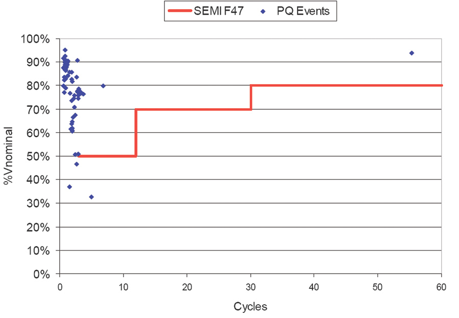
Figure 7: Snack Food Facility PQ Events
As can be seen in Figure 7 above, nearly all of the voltage sags occurred at less than five cycles, with most at or below three cycles. The voltage sags of concern with regard to the ice cube relays in this facility fall below 75%. Figure 8 shows the performance curve of a common ice cube relay (solid black line) overlaying the sag data of Figure 7. Around 16 of the voltage sags (i.e., about 11 per year) could have affected the relays used at this facility. If the AC ice cube relays in the control panel met SEMI F47, the entire panel would likely shut down less than two to three times per year due to voltage sags.
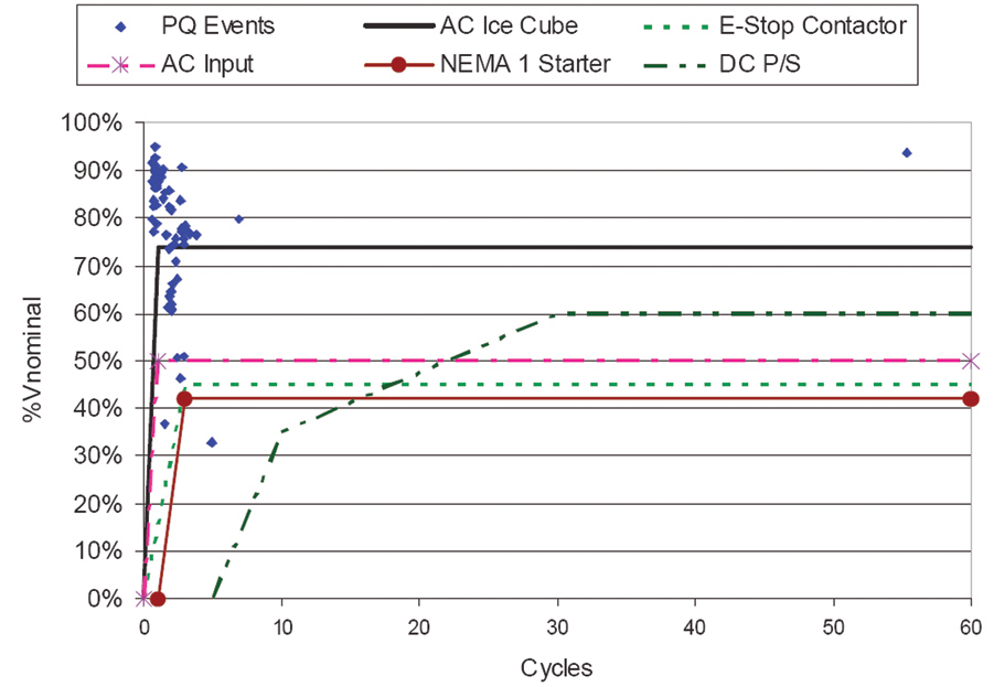
Figure 8: Voltage Sag Ride-Through Data of Various Components in Control Cabinet
Paper Cup Plant
Were AC ice cube relays only rarely used components, the problem they pose would be much smaller in scale. Unfortunately, these ubiquitous relays find application in most if not all electronically controlled industrial and facilities processes. Figure 9 shows four AC ice cube relays in one of the 11 air compressor units used in a paper cup plant. The compressed air is critical to all operations because it is used by the machines for various actuators and to convey the cups from one location to another through a plethora of tube-like conveyors. For this reason, the loss of compressed air in a power quality event causes the entire plant operation to come to a halt.
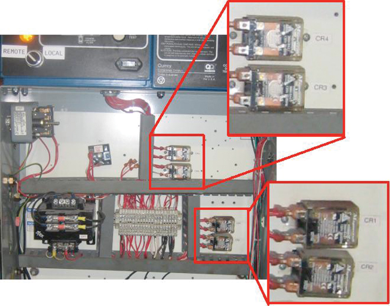
Figure 9: One of 11 Air Compressor Control Cabinets at a Paper Cup Plant
Figure 10 shows a line-to-line voltage sag recorded by a power quality monitor at the plant site. The recorded voltage sag was only 0.96 cycles in duration and was recorded to drop to a value of only 84.9% RMS. However, the actual depth of the sag approached 20% of peak voltage for ½ cycle of the event. This event shut down the plant air compressors thanks to the many ice cube relays in the control scheme.
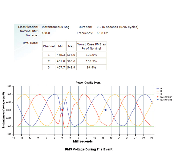
Figure 10: Short Duration Voltage Sag Led to Plant Shutdown due to the AC Ice Cube Relays
Semiconductor Plant
Relatively minor voltage sags can cost a semiconductor plant a million dollars or more. In the late 1990s, EPRI conducted a research project to look into the reason why semiconductor tools were susceptible to voltage sags. Surprisingly, the main reason that most equipment was found to shut down during voltage sags was directly related to the use of AC ice cube relays in their emergency off (EMO) circuit designs.
The EPRI research revealed that of the initial set of 33 tools subjected to voltage-sag testing, almost half were found to shut down due to the effect of voltage sags on the AC ice cube relays used in the EMO circuits, as shown in Table 5, following.
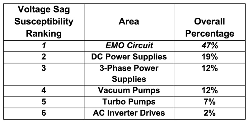
Table 5: Most Common Sources of Voltage Sag-Related Shutdowns in Semiconductor Tools (from EPRI Research)
Typically driven by the smaller EMO pilot relay, the main contactor is used to apply power to the semiconductor tool (Figure 11). If the EMO relay was designed with an AC ice cube unit, the entire tool was found to lose power during many of the voltage-sag tests. This finding helped to lead to improvements in 300-mm semiconductor tool designs. Thus, most 300-mm semiconductor tools are compliant with the SEMI F47 standard. Ironically, due to improvements in wafer-processing technology of 200-mm equipment and economic forces, the lifespan of the 200-mm tools has greatly exceeded what was expected. Therefore, many of the 200-mm designs are still in operation and being supplied to plants today with the vintage EMO circuit designs that include AC ice cube relays.
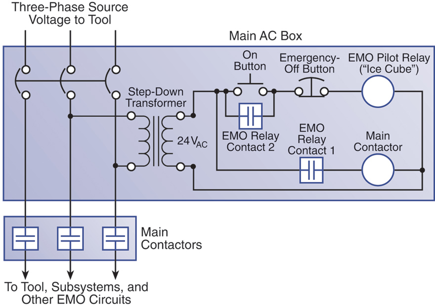
Figure 11: Typical Emergency Off Circuit (Simplified)
Call for Improvement
Modern industry requires a better-designed alternative to the standard AC ice cube relay. If SEMI F47-compliant units are made available, many power quality-related shutdowns could be avoided. Furthermore, industrial plants could be expected to save from several hundred thousands to several millions of dollars each year in downtime and lost revenue. Worldwide, such improvements could have a significant impact.
For this reason, EPRI is calling on the manufacturers of control components* to develop a line of control relays with improved voltage-sag robustness. Ideally, the market cost of the improved relay should not be such that it would inhibit widespread adoption by industry.
In general, the improved designs should meet the following criteria:
- The units should be compliant with the SEMI F47-0706 voltage-sag standard, which requires hold-in capabilities down to 50 percent of nominal for the worst-case test point. The units can drop out for voltages less than 50 percent of nominal.
a. Units that can meet the more rigorous requirement of 40 percent of nominal hold-in (IEC 61000-4-11 and IEC 61000-4-34 standards) would exceed the base requirements.
b. Manufacturers who would like to take on this additional challenge are encouraged to strive for the 40% of nominal hold-in voltage.
- The units should not exceed the physical footprint of existing AC ice cube relay designs with the same number of contacts.
- The units must require “AC” power to operate.
- The units should provide standard contact forms such as double-pole double-throw (DPDT), 3-pole double-throw, and 4-pole double-throw.
- The units should utilize standard socket and pin formats such that the new units can easily retrofit and replace relays in existing applications.
- The pull-in and drop-out operation time of the units should be similar to those of common AC ice cube relays in order to match existing applications. Typical specs range from 9 to 25 milliseconds.
- The dropout voltages should be consistent with typical specifications. Typical specs range from 10 to 30 percent of nominal.
(*Manufacturers who would like to engage in this effort to design and demonstrate their ability to meet or exceed these requirements should contact EPRI.)
The EPRI role in this effort would be threefold:
- Provide a test bed for demonstration of the voltage-sag ride-through performance of the new relay designs. Perform testing and document performance, providing feedback to participating vendors.
- Develop a demonstration effort for actual field application for prototype units where they would be used as replacements for existing ice cube relays in control system applications, documenting performance of the improved designs.
- Coordinate through electric utility funders to provide appropriate information for customers (white papers, brochures, summary test results, case studies, etc.) for the improved performance that is possible with the new technology.
About the Authors
Mark Stephens, PE, is a senior project manager at EPRI for Industrial Power Quality in Knoxville, Tennessee. Mr. Stephens manages research and services work related to Power Quality at EPRI. He is a member of several power quality standards working groups in IEEE and CIGRE. With over 21 years of professional experience, he has solid design experience in industrial control system design, programming, instrumentation, equipment installation and startup and leads EPRI’s related efforts in the Power Quality arena.
Stephens received a BSEE from the University of Tennessee in 1988 and has been a registered professional engineer in the state of Tennessee since 1995.
Alden Wright, PE, CEM (Certified Energy Manager), is a project engineer/scientist for Industrial Power Quality in Knoxville, Tennessee. Mr. Wright’s current research activities focus on industrial power quality, SEMI F47 testing and certification, energy efficiency, retrofit energy savings devices, and the Smart Grid. Mr. Wright joined EPRI in 2001.
Wright received a BSEE from the University of Tennessee at Knoxville TN and earned his professional engineer license and is a registered certified energy manager (CEM).


