
Batteries are among the least expensive pieces of equipment in a substation, and they are the heart that keeps the protection and control system running. Despite this, they are often not maintained properly. NERC standards make battery maintenance mandatory and its requirements are more stringent than those for other equipment. Very specific activities and maintenances schedules are described in PRC-005. Failing to comply with these requirements can reduce the life and performance of batteries, in addition to incurring fines.
This article provides an update of the battery testing requirements specified in the latest revision of NERC PRC-005, focused to illustrate the required testing schedule, and the scope of the two main electrical tests to be performed for a successful battery maintenance program. NERC requirements are summarized next to existing IEEE and NETA battery testing recommendations to provide a quick reference when determining a maintenance program.
The current NERC standard is PRC-005-6, and enforcement of this revision started on January 1, 2016. This standard applies to generation and transmission and distribution providers, with specific protection facilities associated with the Bulk Electrical System (BES). The purpose of the standard is to document and implement maintenance programs for all protection systems affecting the reliability of the BES to keep them in working order.
PRC-005-6 contains five requirements identified as R1 to R5. The batteries are covered by R1, where it is stated that a Protection System Maintenance Program (PSMP) shall be established, and all batteries associated with the DC supply of a protection system must be included in a time-based program described in Table 1-4 of the standard. The rest of the requirements for the protection system allow the owner to enact a performance- or time-based maintenance, or a combination of both.
The Compliance Enforcement Authority is delegated to eight Regional Entities shown in the NERC map (Figure 1).

Figure 1: NERC delegates for monitoring and enforcement of compliance (Source: NERC)
If a utility fails to comply with the standard, Appendix 4B: Sanction Guidelines of the NERC, from the Rules of Procedures, is used to enforce the requirements and apply monetary or non-monetary sanctions. For the monetary sanctions, an initial value range for the base penalty amount is determined by considering the Violation Risk Factor (VRF) assigned to the requirement and the Violation Severity Level assessed for the violation. The intersection of the violation’s VRF and VSL in the Base Penalty Amount Table defines the initial value range that could be applied for each day that a violation continues (Figure 2).
The required maintenance activities of the time-based program are divided according to the type of battery: Vented Lead Acid (Table 1-4a), Valve Regulated Lead Acid (Table 1-4b) and Nickel-Cadmium (Ni-Cd) (Table 1-4c). All of the activities of verification, inspection and testing should be documented and retained as evidence for audits. The time-based maintenance includes four-six, 18-month inspections and six- or three-year performance testing (Figures 3, 4 and 5).
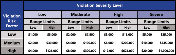
Figure 2: Base Penalty Amount Table from NERC Rules of Procedure (Source: NERC)
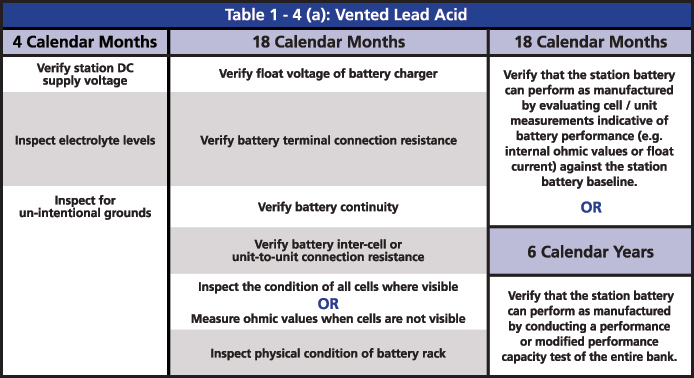
Figure 3: Table 1-4(a): Vented Lead Acid from PRC-005
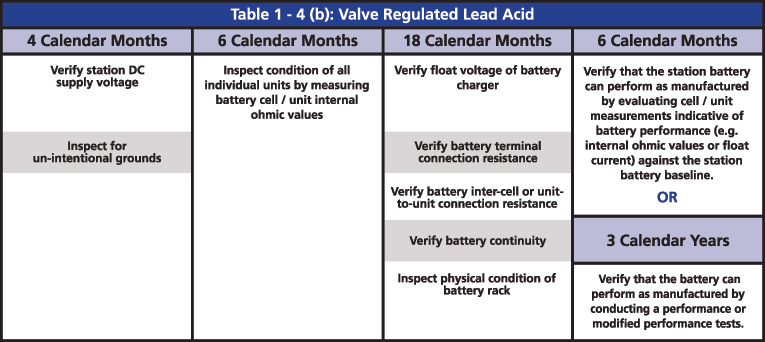
Figure 4: Table 1-4(b) Valve Regulated Lead Acid from PRC-005
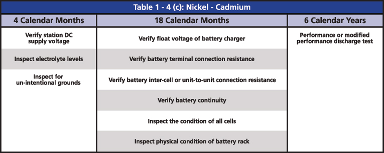
Figure 5: Table 1-4(c) Nickel-Cadmium from PRC-005
The two major tests that are indicated in the activities are the performance discharge test of the battery bank and the internal ohmic values for each cell. The ohmic value measurement in the VLA batteries is an option for when it is not possible to perform a visual inspection, and an option to determine if the battery can perform as manufactured. In the VRLA batteries, ohmic measurement is required every six months, mainly because it is not possible to do a visual inspection. It is also an option to determine if the battery can perform as manufactured instead of running a performance test.
For the Ni-Cd, the only major test that is required is the performance test. In Ni-Cd batteries, neither the nickel nor the cadmium readily dissolves in the alkaline electrolyte; hence, the ohmic value might not change in time. Instead, it mostly remains constant until the battery reaches the end of life, and it might not even change. Therefore, a Ni-Cd battery with an ohmic value different from the baseline is an indication of a problem; however, a value without a change in time does not necessarily mean a good battery.
When defining a PSMP for the battery system, the activities listed in Table 1-4 are the minimum to be included but additional activities can be added according to the needs or conditions of the system. IEEE and NETA have recommendations for battery maintenance that can be used as a reference when adding maintenance activities for batteries.
Figure 6 shows a summary of all the activities listed among PRC-005 (P-blue), IEEE 450 (I-green) and NETA MTS (N-yellow) for VLA and VRLA batteries and their recommended periodicity. Further detailed tables for VLA, VRLA and Ni-Cd batteries can be obtained from http://bit.ly/2iXcdsN.
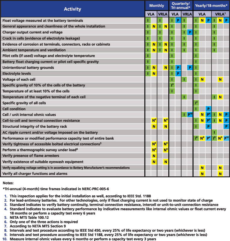
Figure 6: Summary of battery maintenance requirements from PRC-005, IEEE 450 and NETA MTS
Both the ohmic measurement and performance tests have their own specific procedures to obtain proper and reliable results.
Ohmic Measurements:
Pending construction type and health condition, lead acid battery cells will have a characteristic ohmic value. If this value is measured under consistent conditions and good testing practices, the battery can be characterized and trended to identify degradation. As a rule, if the internal resistance or impedance value increases, the capacity of the cell will be reduced; however, there is no direct correlation to apply for capacity calculation and the result is a relative value. Three different technologies are available to measure ohmic values: resistance, conductance and impedance.
For ohmic measurements, the battery should be in electrical, chemical, and thermal equilibrium. To obtain repeatable and reliable results it is recommended to perform the measurements when the battery is fully charged and 72 hours after adding water or charging the battery. Changing floating signal, such as the one influenced by ripple or noise from the charger or the loads will also affect repeatability.
In addition to the requirements above, a constant use of the same measurement technology (instrument type and leads) will guarantee reliable and consistent data for analysis.
Degradation of a cell can be defined based on trending and identifying cells for further investigation, based on a significant modification of the measurement. Figure 7 shows four yearly results of a 60-cell bank.
Three different comparison methods can be used to determine if a cell or the string is deteriorating:
- Variation from each cell measurement when compared to the average value of the string. A high variation from the string average is not necessarily an indication of a bad cell; it may be poor connections causing inadequate charging or need of equalization. This method is for short-term analysis and at the beginning of measurements on a string.
- Change from the previous measurement for each cell. This helps to locate cells that may be about to fail in the mid-term period of the data trending.
- Deviation from a string baseline value established once the battery is installed and fully developed during the first year of life. This helps to identify how much the cells and the string have aged, especially in the long-term of the data trending. If multiple cells have a significant deviation from the baseline, it is an indication of capacity deterioration.
A significant modification is subject to the characteristics of each battery type and manufacturer, therefore it is recommended to trend results and establish specific warning values over time, with knowledge of the battery and consultation with the manufacturer.
For impedance measurements, the following are the recommended evaluation criteria for VLA and VRLA batteries (Table 1). These are a starting point; they can vary depending on the battery or environment and should be adjusted as successive testing and investigation is performed.
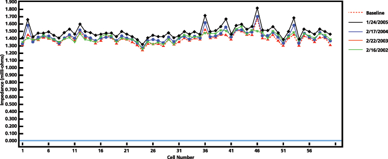
Figure 7: Impedance results of a 60-cell bank. Four consecutive years of testing.
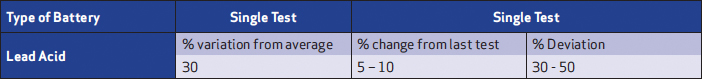
Table 1: Impedance evaluation criteria
An impedance tester provides the voltage of each cell, float and ripple current, and strap resistances in addition to the ohmic value. All of these measurements are included in the monthly, quarterly or yearly requirements, so it makes sense to use one single instrument to perform all the measurements in one single operation for each cell.
Discharge and Performance Test
A discharge test is that in which the battery delivers a current to a load to determine its ability to meet specific criteria such as duty cycle, service or a determined capacity before or at reaching its end of discharge voltage. The voltage of each cell should be monitored throughout the discharge to identify weak cells. The test result will determine if the battery needs to be maintained, or replaced either totally or partially.
The performance test included in the PRC-005 requirements is, in essence, a test to determine the percentage capacity of the battery. The modified performance in addition to the percentage capacity also helps to determine if the battery can meet a specific duty cycle. To run a performance test, the following is required:
- Battery fully charged, in equilibrium, and maintained as per monthly/quarterly requirements
- Record the temperature at the beginning of the test
- Desired discharge time (typically longer than one hour)
- Manufacturer specified constant current or constant power for the desired discharge time at a specified temperature
- End of discharge voltage
- Load bank capable to draw a constant current or power from the battery with the ability to stop the test when the overall voltage reaches the end of discharge level
- Means to measure individual cell voltages throughout the test
The purpose of the test is to determine the true capacity of the battery by finding the time that it takes the battery to reach the end of discharge voltage and compare it to the expected time from the battery specifications. The ratio between the resulting time and the expected time defines the capacity of the battery in percentages. If the temperature of the battery is different from 25 °C (in some cases 20 °C), a correction factor should be applied: %C=(Ta/(Ts*KT))*100. Temperature correction factors are provided in IEEE 450 for lead acid and IEEE 1106 for Ni-Cd batteries.
When defining the desired duration of the test, it is recommended to select a time close or equal to the duty cycle of the battery, to confirm the ability of the battery bank to meet the expected duty cycle, in addition to the capacity.
Furthermore, when performing the test periodically, it is recommended to use always the same duration in order to trend historic results.
The standardized IEEE passing criteria for Lead Acid and Nickel Cadmium batteries are 80 percent capacity. At the beginning of the life of the battery is very common to measure capacities ranging from 90 - to - 110 percent or above. Below 80 percent of capacity, provisions should be taken to replace the battery within a year.
Cell voltages should be recorded throughout the test, but a minimum of three instances is required at the beginning, the middle and at the end of the test. The purpose is to identify weak cells that could be affecting the overall capacity of the bank, or if it is a generalized string deterioration. In lead acid batteries, when a cell reaches the minimum voltage before 90 percent of the completion of the test, it should be bypassed to avoid polarity reversal, which is the moment in which the cell will become a load for the bank.
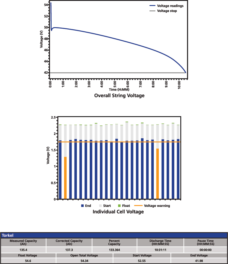
Figure 8: Battery performance test result
If a cell or cells are identified as weak or are bypassed, depending on the age of the battery and the final capacity result, it might be applicable to replace these cells to improve the capacity of the string. If the cells are just removed, not replaced, the charger floating voltages should be recalculated to the appropriate level to avoid overcharging or overvoltage that can lead to permanent gassing and dry-out of the cells.
Considering that the battery might operate with weak cells, or even without them, the question arises of the maximum number of cells to be bypassed. The recommended criterion to define this is by determining the minimum voltage required by the system being supplied by the battery to avoid reaching under-voltage limits.
Bypassing a cell should be done in a maximum of six minutes, which requires preparation and appropriate practices to avoid accidents. Hence, the decision should be based on the proper amount of data from the cells. Measuring the cell voltage in prolonged intervals might lead to a late identification of a weak cell risking a polarity reversal in lead acid batteries. Technology now allows monitoring the voltage of each cell throughout the test and identifying weak cells accurately and in a timely manner.
The typical result of a performance test includes the overall voltage curve during the discharge and the capacity calculation. This is complemented with overall and individual float voltage before turning off the charger, open circuit voltage before starting the test, as well as the start and end voltage. If there is any pause during the test, it is also important to document it to show that the time limit was not exceeded. Figure 8 presents a simplified example of a performance test result.
A performance test provides an absolute result and is the only way to determine exactly the state of health (SOH) of the battery. However, it is a test that can be resource-demanding and might require having available a backup during the test and the recharge of the battery to avoid unavailability of the equipment backed up by the battery.
On the other hand, ohmic measurements, like the impedance method, provide a relative measurement. When performed under consistent and good testing practices provides a simple and comprehensive online method to assess the condition of the string and each cell. This can be used to determine further investigation or to decide the replacement of a cell or the entire string. It also provides extra measurements that are required by the standards and regulations on regular maintenance testing.
Proper PSMP implementation requires considering the type of batteries, the standards and regulations, available resources and specific conditions or needs. Reviewing the standards provides the necessary references, but it is very important to understand and know what testing equipment can do, so it is selected properly to meet the testing needs and assure efficiency and accuracy during the maintenance activities.
 Volney Naranjo is senior applications engineer at Megger. He has more than 16 years of experience working in the power engineering industry, providing professional services for design, and testing and commissioning of power systems as field engineer and project manager. Volney has been working with Megger for more than six years as an application engineer focusing on power transformer, high voltage circuit breaker, battery and power quality testing. He graduated in 2001 from the University of Valle in Cali, Colombia with a Bachelor of Science in electrical engineering and is a member of IEEE-PES.