


Preface
The interruption of electric power circuits has always been an essential function, especially in cases of overloads or short circuits when immediate interruption of the current flow becomes necessary as a protective measure.
In earliest times, circuits could be broken only by separation of contacts in air followed by drawing the resulting electric arc out to such a length that it can no longer be maintained.
This means of interruption soon became inadequate and special devices called circuit breakers had to be developed.
The basic problem has been to control and quench or extinguish the high power arc, which necessarily occurs at the separating contacts of a breaker when opening high current circuits.
Since arcs generate a great deal of heat energy, most often destructive for the breaker's contacts, technology had to find ways to limit the arc duration and develop contacts that can withstand the arc effect time after time.
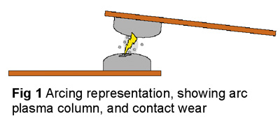
In the present article you will find a summarized description of the different designs of make/break contacts found in the modern power circuit breakers and the key factors influencing their architecture and material choice.
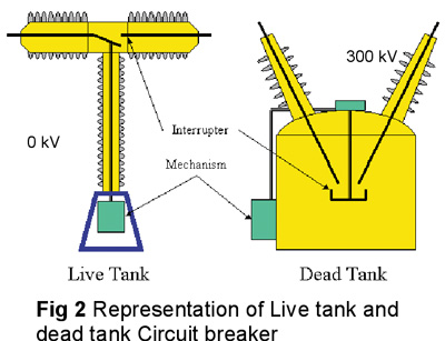
INTRODUCTION
Since the beginning, scientists based their research on exploring the capabilities of the available quenching mediums. Hence the breakers are classified accordingly.
The arc quenching ambients are numerous.
Historically, it should be mentioned that pure water has had some use in Europe. The arc produced gases, steam and hydrogen, which are as effective as the vapor and hydrogen from oil in quenching the arcs, but insulation problems have limited the use of this medium and at present no breakers are being built that use this technique.
For the purpose of the present article, we will limit our quest to those most popular: Oil, Compressed air, SF6 and Vacuum.
Breaker Categories
Breaker development research has explored the available mediums and has come up with a lot of breaker designs but most of them fall into four major categories:
Oil circuit breaker
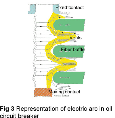
In oil circuit breakers, the arc is drawn in oil inside a special compartment of the interrupting chamber called the explosion pot. The intense heat of the arc decomposes the oil and produces gases, mainly composed of hydrogen, generating high pressure that produces a fluid flow through the arc and out of the explosion pot through vents situated on its walls. Thus extending the arc’s column and carrying its energy away until its total extension see Fig 3.
At transmission voltages below 345 kV, oil breakers used to be popular. They are increasingly losing ground to gas-blast circuit breakers such as air-blast breakers and SF6 circuit breakers.
Air-blast circuit breaker
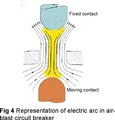
In air-blast circuit breakers, air is compressed to high pressures. When the contacts part, a blast valve is opened to discharge the high-pressure air to the ambient, thus creating a very-high-velocity flow near the arc to dissipate the energy.
SF6 circuit breaker
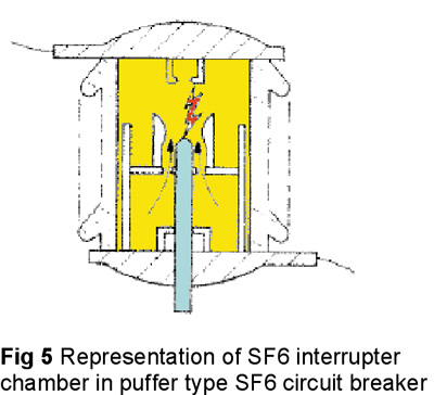
In SF6 circuit breakers, the same principle is employed, with SF6 as the medium instead of air. In the “puffer” SF6 breaker, the motion of the contacts compresses the gas and forces it to flow through an orifice into the neighborhood of the arc. Both types of SF6 breakers have been developed for EHV (extra high voltage) transmission systems.
Vacuum circuit breaker
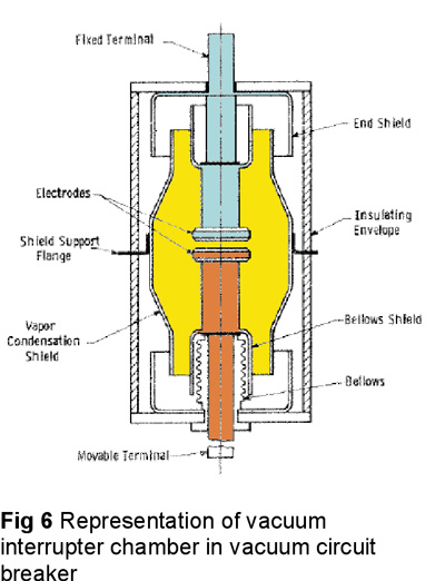
The vacuum breaker uses the rapid dielectric recovery and high dielectric strength of vacuum. A pair of contacts is hermetically sealed in a vacuum envelope.
Actuating motion is transmitted through bellows to the movable contact. When the contacts are parted, an arc is produced and supported by metallic vapor boiled from the electrodes. Vapor particles expand into the vacuum and condense on solid surfaces. At a natural current zero the vapor particles disappear, and the arc is extinguished. Vacuum breakers of up to 242 kV have been built.
Make/break contacts
The breaker’s heart is the switching element.It is where the arc quenching takes place. It mainly contains the make/break contacts and the interrupting medium. The make/break contacts’ functions can be reduced to:
• Conduct the electric current when the breaker is closed.
• Withstand the arc’s destructive effect while interrupting.
Generally, the make/break contacts have a stationary part and a moving part. By bringing the moving part to touch the stationary one, electric current flows and the breaker is closed.
By driving the moving contact away from the stationary contact the electric arc develops and by quenching it the current stops flowing and the breaker is open.
Contact design and choice of materials are greatly affected by the arc's energy, duration and the chemical reactions that may occur with the ambient medium under the arc’s effect.
To understand these crucial elements, it is necessary to review the electric arc’s characteristics.
Electric arc
The electric arc is a natural phenomenon. Despite its destructive nature it is of great use to current switching in circuit breakers. It acts as variable impedance from zero value when the breaker is closed to infinity when the breaker is open.
High-Pressure Arc
Found in blast type circuit breakers (air-blast, SF6 and oil circuit breakers). Great heat generation and relative long durations characterize them. They also generate deposition of solid by-products that may affect the conductivity of the contacts.
Vacuum Arc
Found in vacuum circuit breakers. They are limited and of short duration. They cause no deposition of by-products.
Contact Architecture
For high-pressure arcs:
The contacts have to withstand the arc’s heat without excessive damage. They also need to have good conduction properties.
Tungsten and tungsten alloys have good resistance-to-arc properties but less conductivity. Copper and silver have great conductivity but relatively poor resistance-to-arc properties.
The contacts have also to overcome the deposition of by-products that may become a problem if not wiped off before an insulating layer is built.
The type of contacts that are commonly found in these types of devices are:
Sliding contacts
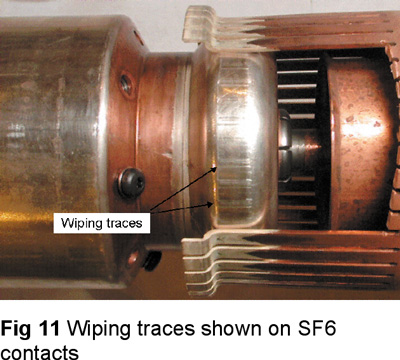
As their name indicates, the moving contact and the stationary contact touch on closing and slide into each other to a certain distance before stopping at closed position. On opening, they slide out until their separation and the arc's ignition. The sliding action helps to wipe off the deposited by-products, to make better contact on closing.
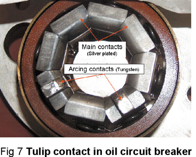
This type of contact usually separates the resistance-to-arc role from the current carrying role, by using tungsten alloy based contacts called arcing contacts that are meant to close first on closing and separate last on opening and are submitted to the arc. The current carrying role is attributed to copper or silver plated copper contacts called main contacts. These contacts are not subjected to the arc and therefore not eroded by it.
Design examples
Designers worked hard to reach effective designs exploit these principles.
In the KSO type oil circuit breaker by the General Electric company, the stationary contact is a ring of sprung copper (or sliver plated) contact fingers where two of them have a tungsten tip (see Fig 7).
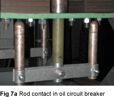
The moving contact is a solid rod of copper (or silver-plated) with the upper part made of tungsten (see Fig 7a)
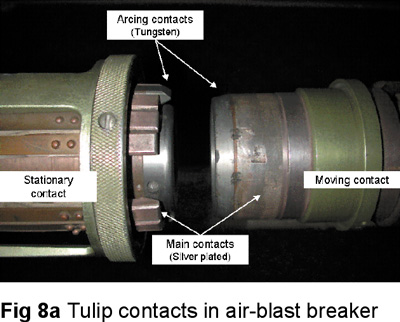
In the Dell-Alsthom, PKV type air-blast circuit
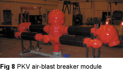
breaker, the stationary contact is a tulip contact made of sliver plated copper contact fingers where two of these contacts are arcing contact fingers made of tungsten. The moving contact is a tube of silver-plated copper with the upper part made of tungsten (see Fig 8a).
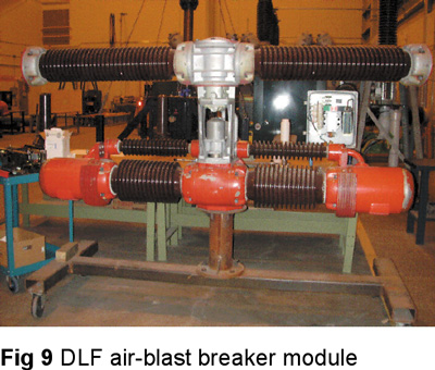
The ABB, DLF Type air-blast circuit breaker uses butt contacts which are particularly shaped to achieve these goals.
In SF6 ABB, HPL Type circuit breaker,
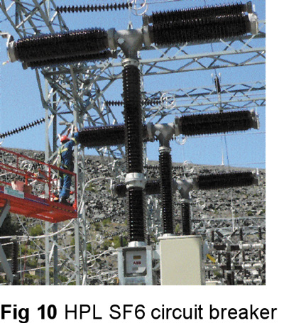
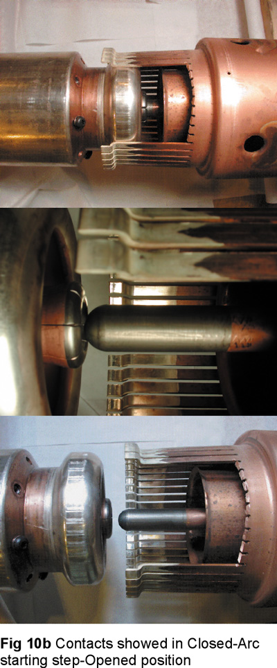
For main contacts the stationary contact is a tulip contact made of sliver plated copper contact fingers, the moving contact is silver-plated copper tube The arcing contact is completely separate from the main contact. The stationary contact is a tungsten rod and the moving one is a tulip consisting of tungsten contact fingers.(see Fig 10a)
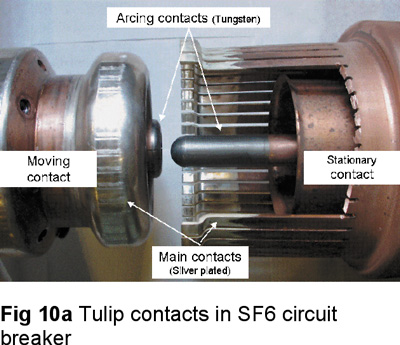
All of these contacts use a wiping action when the moving contact gets inserted in the stationary contact as we see the traces of this action in Fig 11.
For Vacuum arcs: none of the above conditions are present. Two plates of conductive material can constitute the moving and the stationary contacts. Generally we need to separate them to a short distance (3mm to 20mm).
In a vacuum circuit breaker, vacuum interrupters are used for breaking and making load and fault currents. When the contacts in vacuum interrupter separate, the current to be interrupted initiates a metal vapor arc discharge and flows through the plasma until the next current zero. The arc is then extinguished and the conductive metal vapour condenses on the metal surfaces within a matter of microseconds. As a result the dielectric strength in the breaker builds up very rapidly.
The properties of a vacuum interrupter depend largely on the material and form of the contacts.
Over the period of their development, various types of contact material have been used. At the moment it is accepted that an oxygen free copper chromium alloy is the best material for high voltage circuit breakers. In this alloy, chromium is distributed through copper in the form of fine grains. This material combines good arc extinguishing characteristic with a reduced tendency to contact welding and low chopping current when switching inductive current. The use of this special material is that the current chopping is limited to 4 to 5 Amps.
At currents under 10kA, the vacuum arc burns as a diffuse discharge. At high current values the arc changes to a constricted form with an anode spot. A constricted arc that remains on one spot for too long can thermally overstress the contacts to such a degree that the deionization of the contact zone at current zero can no longer be guaranteed.
To overcome this problem, the arc root must be made to move over the contact surface.
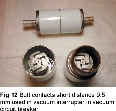
In order to achieve this, contacts are so shaped, as in Fig 12, that the current flow through them results in a magnetic field being established which is at right angles to the arc axis. This radial field causes the arc root to rotate rapidly around the contact resulting in a uniform distribution of the heat over its surface. Contacts of this type are called radial magnetic field electrodes and they are used in the majority of circuit breakers for medium voltage applications.
A new design has come in vacuum interrupters, in which switching the arc from diffusion to constricted state is done by subjecting the arc to an axial magnetic field. Such a field can be provided by leading the arc current through a coil suitably arranged outside the vacuum chamber. Alternatively the field can be provided by designing the contact to give the required contact path. Such contacts are called axial magnetic field electrodes.
This principle has advantages when the short circuit current is in excess of 31.5 kA.
Testing
Make/break contacts as presented need to be tested periodically to assess their condition. These contacts have to keep their good conductive properties when the contacts are fully closed. The conductive properties may be affected by the mechanical wear due to friction on operation or electrical wear caused by the electrical arc.
Contact resistance measurement:
The best method for testing contact resistance is to put in application Ohm’s law. It consists of applying a current, usually 100 Amps, and to measure the voltage drop in volts across the closed contacts. The resistance is then calculated in dividing the voltage by the current. The resulting value is read in micro-ohms, 1 micro-ohm= 10-6 ohms.
This measurement is used on all types of contacts.
Dynamic contact resistance:
For some breakers, especially those that use an arcing nozzle to drive the flow of the quenching medium (puffer type SF6 breakers for example, see fig 10b), the wear of arcing contacts, if excessive, may affect the arc quenching capability of the interrupter, resulting in its destruction.
So the assessment of the arcing contact cannot be done by simply measuring the contact resistance in the classic way as described previously. A new method is developed called the dynamic contact resistance. It consists of measuring the contact resistance as described above but continuously while the contact is moving from the first contact touch until the fully closed position. This method permits to measure the length of the arcing contact and by comparing it to a value measured when new, helps determine its state of erosion.
It is important to state that this method does not apply to butt-type contacts.
Summary
The electric arc plays an important role in the choice of material and shape of the make/break contacts.
In high-pressure arcs, intense heat is generated, which the contacts have to resist and keep their conductive properties. This is achieved by using tungsten alloys and copper or silver- plated copper and tulip contacts shape.
In vacuum arcs, the choice of materials is crucial to limit vapor emissions and favor their condensation within microseconds otherwise the contacts are destroyed. Oxygen-free copper chromium alloy is the best material for high voltage circuit breakers and butt contact shape is commonly used .
Bibliography
The present article is based on our personal experience.
• Power circuit breaker theory and design, edited by C.H. Flurscheim, revised edition 1982;
• Circuit Interruption theory and techniques, edited by Thomas E. Browne Jr., edition 1984;
• Contact material, Proc. 9th Int. Conf. Electr. Contact phenom./24th Holm Conf. Electr. Contacts, IIT, Chicago, September 1978, pp. 81-86.
• JK. Lemelson, The failure of closed heavy current contact pieces in insulating oil at high temperature, Proc. 6th Int. Conf. Electric contact phenom., IIT, Chicago, June 1972, pp. 252-258;
• R. Holm and E. Holm, Electric Contacts: Theory and Application, Springer-Verlag, New York, 1967, pp. 89, 136, 161, 438;
• COMPARISON BETWEEN VACUUM AND SF6 CIRCUIT BREAKER FOR MEDIUM VOLTAGE on http://www.panickker.net/article6.htm
• Circuit breaker: Definition and Much More from Answers.com Science and Technology Encyclopedia.
About the Authors
Stéphan Perron, Hydro-Québec teacher, High Voltage breaker maintenance Stéphan Perron has been teaching maintenance and trouble shooting of High Voltage Circuit Breakers and Thermography for more than 7 years at the Hydro-Quebec Competence Center based in Saint Antoine des Laurentides, QC, Canada. He developped his expertise by working on the maintenance side of the High Voltage Circuit Breakers of Hydro-Quebec for 18 years. His specialties are the ABB (models SFE, HPL, ELF and DLF) breakers, the GE (models KSO, AT) breakers and all the related test instruments, as well as the sectionnors Joslyn VBM, the handling and behavior of the SF6 gaz and interpretation of thermagraphic readings (Level 1) on breakers. Stéphan Perron holds a DEC degree in Electronics from the CEGEP St Jérome, QC, Canada
Emile Nasrallah is an electrical engineer specialized in Power circuit breakers maintenance. Since graduation in 1984 he worked as a field engineer. In1990 he joined the worldwide circuit breaker manufacturer GEC ALSTHOM as a specialized field engineer.In 1997 he became the manager of MV & HV circuit breaker SF6 division of ALSTOM, responsible of technical support, maintenance and training for SF6 circuit breakers. In 2001 he became manager of Air blast circuit breaker division for AREVA. He was in charge of the Air blast (PK and PKV) refurbishing program in partnership with hydro-Quebec and introduced a unique administration system for the program (average of 35, 735 kV PK air blast circuit breaker per year). In 2005 he joined General Electric Company of Canada as a senior circuit breaker specialist and is in charge of the circuit breaker division of the Montreal service centre, responsible of the remanufacturing program for Oil circuit breakers
Dr. Fouad Brikci is the president of Zensol Automation Inc. He was the first to introduce the concept of truly-computerized test equipment in the field of circuit breaker analyzers. As a former university teacher in Ecole Polytechnique — Algiers and CNRS - LAAS researcher in France, Dr. Brikci has developed experience in the fields of electronics, automation, and computer science. Most activities were focused on the industrial application of computers. Among his achievements are the development of fully comput¬erized measuring systems for quality control in circuit breaker manufacturing, laboratories, and maintenance services of electric utilities. Dr. Brikci holds a PhD in Electronics and a Master in Sci¬ences in EEA (electronics, electrotechnics, and automation) from the University of Bordeaux, France. http://www.zensol.com, email : zensol@zensol.com Fouad Brikci, Zensol Automation Inc.


