A vital trend in electrical testing technology that has been gathering momentum is the consolidation of features and functions. This is worth looking into when searching for new or replacement testers, as you may be able to “kill two (or more) birds with one stone,” as the expression goes. You may not necessarily have to replace, say, an insulation tester with another insulation tester, but may be able to take advantage of a multifunction tester that does much more.
For the first half of the 20th century, development of electrical test equipment was relatively slow. The instruments were just fine for what they did, but they generally focused on between one to three functions. The individual testers manufactured by high-quality brands were sometimes literally signed off by the final technician on a plate or permanent label because they were expected to last ad infinitum. And believe it or not, some are still in use to this day. But reference resistors, decade switches and analog displays fairly limited what could be done with a single instrument. For many jobs, you needed many boxes.
Innovation: The mother of invention
Innovation began to pick up after mid-century and took a quantum leap with the introduction of microprocessor technology circa the 1970s, continuing its momentum right into the 21st century. Multiple functions and applications can now be coordinated in a single handheld tester. Remember, however, it is never a bargain to replace two good-quality testers with one mediocre one. A promotion may trumpet the many things that a multi-function tester can do, and this can be impressive, but you need to be aware of what you are purchasing. The good news is that in electrical testing, there are independent standards and SOPs that can separate the “real deal” from the “wannabes.”
Knowing what to look for in a tester
When searching for a multi-tester, it is important to be on the lookout for certain features. One of the most important features a tester should have is protection against arc flash/arc blast, which can be lethal to the operator. Verbal claims like “safe” mean nothing. Fortunately, there is an international standard that rates this protection with a numbering system. It is essential that whatever tester you choose is rated as such. The standard you should be on the lookout for is IEC 61010-1. Be familiar with it and always use an instrument that is correctly rated for the testing environment.
Remember, as instruments become smaller, manufacturers are presented with a design challenge to keep them safe from deadly internal arcing. The IEC rating tells the operator where the instrument can be used safely. If there is no rating provided, don’t buy the tester.
Measurement is still the core function of any electrical test, so when choosing an instrument to purchase, this should be top of mind. Many operators still like the interplay between tester and test item that they get with mechanical analog results, but liquid crystal displays are a quantum leap in accuracy and resolution. These displays provide a wealth of additional data, including voltage, current and resistance in a single test, as well as make vital checks on test conditions, like noise interference. And the old-timer’s favorite, pointer travel, may be made available electronically. But it may be of interest to determine that what you’re seeing is a true logarithmic arc and not just a curved bar graph. In the latter case, the travel could be misinterpreted and result in a wrong conclusion.
Be wary of the ‘jack of all trades and master of none’
With electrical testing, and especially maintenance and troubleshooting, one of the wisest observations is that “time is money.” Test equipment is primarily viewed in terms of the measurement, and rightly so, but consider ease of use and speed as well. These have been notably improved in recent decades. Size reduction can put a whole toolbox of instruments into one. But when looking at multiple functions, be careful and remember that quality is still the prime importance. Be careful of instruments that do a lot of things, but none of them well. That is no longer necessary. Both multiple functions and high-quality measurement are available in single instruments. Also, be careful of instruments that have a few popular functions well developed at the expense of more basic or limited ones that can stall your testing over critical issues.
It is possible to have it all in one tester
Safety, function, accuracy and speed of testing can all be brought together in a single piece of test equipment. Consider the tasks at hand and in many cases, they may be included together in a single test instrument. A common task is proofing an electrical facility against NFPA 70, commonly referred to as the National Electrical Code. This is a widely respected document that assures that an electrical facility is safe. It doesn’t focus on maximum efficiency or performance; however, it does assure that the facility has been tested and proven safe against hazards like electrocution and fire. The electrical plant can be given a final check before being brought online. The circuitry is tested for integrity and proper grounding. A single piece of multi-function test equipment can do this.

Figure 1 – Multi-function testers skillfully combine form and function to provide both speed and accuracy.
The core functions performed by a multi-function tester for NFPA 70 are insulation testing and ground testing. There are other functions as well, for the convenience and safety of the operator. The testers are small, lightweight, approximately 2 pounds and easily handled. Selector switches are a major convenience for the operator. Membrane switches belong in the lab. In the field, the operator may be wearing safety gloves and needs to be able to just turn a switch to a desired function and be ready to test. Complicated setup procedures need to be reduced or eliminated. If there is a pause or distraction, the operator merely looks at the instrument panel to see where he or she is in the testing process.
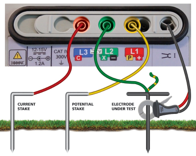
Figure 2 - Integrated color coding of instrument and leads makes setup easy and eliminates mistakes.
Insulation testing
The insulation test confirms the integrity of wiring and equipment by applying a test voltage across the insulation and measuring the leakage current that gets through and then converts this to a resistance. Considering that the human body generally interprets 5 mA as a shock, with 0.5 being the lower limit of perception, it is apparent that any leakage should be limited to the nano-amp or even pico-amp realm.
Consequently, an insulation test should produce a result well into the megohm or even gigohm range. On new wiring, don’t be surprised if you test all day and get nothing but over-range readings. That’s good. But if a carpenter drove a nail through the wiring and shorted it out, that will appear as a zero or something down in the kilohm (kΩ) range.
Judicious placement of the alligator clips that apply the test voltage across the insulation is key to either quick or exhaustive testing. This is often at the operator’s discretion. For instance, all three phases can be tested to ground at once. The more that is put on the tester, the lower the reading will be. Hence, if a nice, comfortably high reading is attained, then each phase would read higher if tested individually. It is not necessary to go to this length. On the other hand, if the operator wishes to be completely thorough, then every combination – phase to phase, phase to ground, etc. – can be tested individually. The tester will typically have a test voltage selection, such as 100, 250, 500 and 1 kV. A 500V test is universal for building wiring, with 1 kV for troubleshooting because incipient damage or flaws may be revealed at the higher voltage. For more sensitive circuits, like telecom/datacom, computer and other such equipment, the lower test voltages may be appropriate.
Ground testing
A click of the insulation selector should move the operation to the ground test selector. This will verify that there is an effective ground rod or other grounding electrode in place, and at sufficiently low resistance to safely divert any fault current into the earth and not through equipment or people. The test is performed with long leads and metal probes driven into the soil at some distance. The far probe establishes a distinct test current through the soil. Unlike the dc insulation test, this is done at an alternating square wave to have a distinctly recognizable signal apart from noise traveling in the soil. The second probe senses voltage drop from soil resistance, and the two measurements are combined to produce a resistance shown on the display. The Code is forgiving in this regard, specifying 25 Ω or less, or a second driven rod. This may do for residential grounding, but for commercial and industrial, a much lower value, 5 Ω or less, is recommended.
The ground test function typically will have selections for terminals engaged. A 2-pole function performs an important corollary to ground testing; that is, bonding. All the grounding conductors from equipment to bus should be tested for low resistance continuity. This can be readily accomplished by a selector position making a 2-pole tester, much like a DMM, but with the advantage of the long leads used for ground testing.
The 3-pole position is for the core ground test - tested electrode, current and voltage probes. Also, a tester may offer current and voltage clamps. Used in tandem, these can substitute for the long leads and setup time by performing a clamp-on ground test. But never do this until you’ve learned the limitations of the method…shorts and opens…otherwise it could be merely a waste of time. Used alone, the current clamp can be a valuable tool in proofing the electrical system and troubleshooting problems.
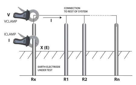
Figure 3 – Schematic for typical clamp-on ground resistance test
Continuity and voltage functions are important too
Continuity and voltage functions are almost automatic in such testers, as they are already included in the more complex measurements. But they give the operator two additional tools for measuring, checking and proofing the circuitry, plus in the case of the voltage meter, added safety. And it’s a good idea to consider an instrument that has storage and downloading. It can be as simple as pressing a button to store a result and it can save you headaches later on when dealing with customers, clients, inspectors, insurance and even legal cases.
In the old days, dual- or multi-function instruments were sometimes little more than two or more boxes stitched together, with little integration of function. Twenty-first-century technology makes it possible to have the best of both worlds – an instrument that not only performs multiple functions but also does them all well. And that saves the operator time and reduces or eliminates errors.
 Jeff Jowett, senior applications engineer for Megger has more than 40 years of experience in application and instrumentation. A recognized industry expert, Jowett is a frequent presenter to industry organizations including NETA and NJATC, has written numerous articles for trade journals, presented seminars and conducted multiple industry training sessions. He is a member of IEEE and the committee for the revision of Standard 81, Recommended Guide for Measuring Ground Resistance and Potential Gradients in the Earth. He received a B.S. in biology from Ursinus Collet in Collegeville, PA.