Forward
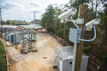
Video monitoring is a key component of an electric utility’s comprehensive physical security plan. For utilities following NERC CIP 014 and the NERC Security Guideline for the Electricity Sector, a video system is required to visually monitor substations and prevent and investigate various types of security threats including theft, unauthorized access, vandalism and sabotage to the critical infrastructure. Unmanned remote sites provide an easy target for intruders, and security threats are constant with the theft of copper and damage to high-value electrical components and material. Theft and vandalism not only cause loss of equipment and revenue but are also a danger to the public, utility personnel, and the intruder, as these actions could affect the performance of the live system.
Installing a video system in a remote substation comes with challenges that are unique to the industry, including, high levels of EMI, voltage surges and interrupts, limited network bandwidth, and extremes in weather conditions. These challenges should be considered if the utility’s goal is to have a reliable, low maintenance system that will still provide the necessary features and performance. This article outlines the key requirements including the design, communications architecture and hardware specification that utilities should consider when purchasing and installing a video system.
Introduction
Installing a video monitoring system is one of the first steps that a utility will take when implementing a physical security plan. A comprehensive video system can cover several of the eight concepts in the NERC Security Guideline for the Electricity Sector: Physical Security. While the NERC guideline covers the concepts including suggestions to use a video monitoring system, it does not provide the user with suggestions on how to implement a system that is suitable for a substation environment, the communications network or associated protocols.
Environmental Conditions in a Substation
Electromagnetic Radiation
A high-voltage transmission substation can operate at 500kV or higher. At this voltage level, the electric current flowing through the power lines produces an electromagnetic field that can extend to more than 300 meters. The Electromagnetic Field (EMF) causes interference and misoperation in electronic equipment if the equipment is not designed to mitigate the effects. The disturbances generated by high voltage lines, switchgear, breakers and other apparatus in the substation are known as Electromagnetic Interference (EMI) or Radio Frequency Interference (RFI). Electronic equipment that operates in the vicinity of high voltage apparatus must be designed with immunity to this type of interference to avoid misoperation and loss or corruption of data.
Electrostatic Discharge (ESD)
Because there are large fields of electromagnetic radiation in substations there is a higher probability for electrostatic charges to build up and cause damage. The ESD charges are released when there is contact or near contact with a grounded object at lower voltage potential. The contact can occur from the charged body of a worker or through a tool that is being carried to a grounded object. If the grounded object is a piece of electronic equipment, the high voltage will flow through the circuits and cause damage or destruction to components, if the circuits are not properly protected. To provide proper protection from high levels of ESD the chassis and all network and communication ports on electronic equipment must provide a path to ground that avoids sensitive circuits.
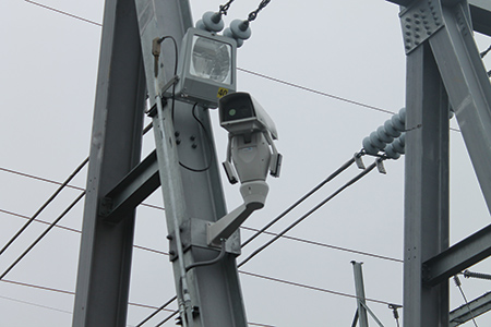
Cameras that operate in close proximity to high voltage lines require immunity to the effects of EMI.
Instability of Power Supply
Substations, where the voltage supply is transformed and switched to and from different voltage levels and circuits, causes voltage ripples, surges and interrupts on the primary power supply that is used for electronic equipment in the substation. Load switching from faults in the electrical system can also cause ground potential rise.
Electronic equipment in the substation must be designed to withstand interruptions and operate seamlessly under many variations of power sources, including switching from primary AC power to backup AC or DC power, when the primary power source fails.
Lightning
Due to the nature of substations being built with tall metal structures in remote areas, they are naturally more exposed to lightning strikes. Even though many substations are designed with sophisticated lightning protection and grounding systems, there are many substations with no lightning protection. When lightning protection is employed, it generally covers a 30º arc under the lightning protection cable and often does not protect the fence line where the camera poles can be located. Even with proper lightning protection in the substation, problems can still arise from voltage surges and ground potential rises for electronic equipment that is not designed to withstand it. Electronic equipment must not only be designed to withstand voltage surges but must also be installed correctly with particular attention to proper grounding.
Extremes in Weather and Climate
While some modern substations have control rooms that are climate controlled, the vast majority of remote substations are unmanned and without climate control. Even if the control room is climate controlled the electronic equipment is expected to operate reliably in outdoor environments with or without equipment cabinets. The equipment must be able to withstand extremes in high and low temperature and humidity. Equipment that operates outdoors must have the correct ratings to be protected from sun, dust, dirt, wind, rain, snow and ice. The operating temperature ratings must not rely on the use of fans as moving parts are usually the first point of failure.
Designing for the Effects of the Substation Environment
Eliminating the Most Common Failures
The components in electronic devices that are most likely to fail are 1) power supplies and 2) motors. High-reliability equipment designed for substation use should be designed with redundant power supplies that can be powered from independent sources. This provides redundancy on the unit’s own power supply as well as from the power source. If the primary AC source goes down the unit can draw DC power from the substation battery to keep running. Secondly, the electronic equipment should be designed without moving parts such as spinning drives and cooling fans/ filters. Substations in remote locations are difficult to access and perform maintenance on and the mechanical components are among the first things to fail. The substation standard specifies equipment must operate at full specified temperature ratings without cooling fans so they are virtually maintenance free.
Fiber Optic Cables
If the communication links inside the substation are copper based they are potential paths for voltage surges as well as being excellent receptors for EMI. Using fiber optic cables for communications in the substation is a common practice to both eliminate these potential sources for interference and failure and also to provide a longer communication path between devices. Copper Ethernet cable standards limit the distance to 100 meters between devices, whereas fiber optic cable can communicate over several kilometers.
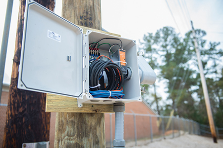
A junction box provides fiber optic communications and power for the cameras
Substation Standards
Substation Engineers recognized the fact that intelligent electronics devices (IEDs) would be increasingly used in substations. They also knew that they had to be designed differently to work reliably in the challenging environmental conditions. The IEEE created a standard known as “IEEE 1613 Standard Environmental and Testing Requirements for Communications Networking Devices Installed in Electric Power Substations.” Along the same lines the International Electrotechnical Commission, (IEC), created a standard known as IEC 61850-3. This standard, “defines the general requirements, mainly regarding construction, design and environmental conditions for utility communication and automation IEDs and systems in power plant and substation environments.” The IEEE standards are more recognized in the U.S. while the IEC standards are more recognized globally but both provide a minimum level of requirements for substation electronic devices. It is generally a requirement for IEDs being used in a substation to meet the requirements of either one or both of these standards. For a manufacturer that markets products globally, it is common for them to ensure their products meet both standards.
Video Monitoring Design for Low Bandwidth Communications
Many substations have minimal communications to remote substations. These networks were originally designed to provide SCADA communications between the substation and the control center to provide remote monitoring of the power system. SCADA systems generally require small amounts of bandwidth and a utility will often require the video system to use the same low bandwidth communication path. Streaming video can take up large amounts of bandwidth and overwhelm existing connections, therefore, it is preferable to process the video at the remote substation and only stream video when an event is detected. The video analytics such as motion detection, boundary crossing, tampering, loitering etc. should be done at the substation, and if an event is detected, an alarm can be generated and sent to an operator. The operator can then open a video stream to investigate further. This design conserves network bandwidth and prevents the operator from having to manually monitor the video feeds.
Network Design
Modern Industrial Video Monitoring Systems use digital technology to send images over an Internet Protocol (IP) network. An IP network is commonly used for Internet connections and corporate LANs making it a very common and easy to use and deploy technology. Use of IP technology allows video systems to be connected to existing corporate networks and to be managed by existing personnel and policies minimizing installation costs and training. IP networking techniques allow the video system to be secured and segregated from the Internet and from the corporate LAN but remain connected to the control center and the SCADA network. As an example, video systems from several substations can be accessed for viewing from the control center, connected to the energy SCADA system and connected to a remote archive server, all over an IP network.
Design for Security
Substation automation networks are industrial, process-based networks that run critical applications to keep substation equipment and the power system protected and running safely. Process-based communications are machine-to-machine, so uninterrupted and timely delivery of data is critical to keep processes running correctly. Process-based networks must, therefore, be kept isolated from the Internet and other corporate traffic to ensure that the data flow is secure and free of losses. In an IP network, technologies such as Virtual Private Networks, (VPNs), subnets and firewalls are used to keep the substation network isolated from the rest of the corporate LAN. The video monitoring system is connected to the substation network so it can communicate with the SCADA system at the control center with alarms, messages, visual, and thermal information of the operating conditions at the substation. The information can be fed into the control system for automated responses or for operators to make decisions and take actions. Since the substation network requires access privileges, the video and SCADA systems are not accessible to personnel without proper authorization and authentication.
Design for Resilience
During the April 2013 attack on the Metcalf substation in California, the first thing the attackers did was cut the communications lines that served the substation. Attackers with a high level of knowledge will know how to disable primary communication networks that link the substation to the control center. The primary link between a substation and the control center is typically a physical cable, either utility owned or leased from a network provider. The video monitoring system network can be designed to mitigate the risk of this cable being disabled by:
Local or network edge processing of video – if the processing capability of the video system is inside the substation – can continue to analyze and record video, even if the connection to the control center goes down. The system analytics will detect events at the substation and generate alarm messages. The video recordings done locally can be recovered for post-event analysis.
Providing a secondary backup link can provide communications if the primary link becomes disabled. This can be a private wireless network or a carrier-based cellular network that will re-route the signals when the primary network fails. The system generated alarms and video can continue to be viewed over the wireless network.
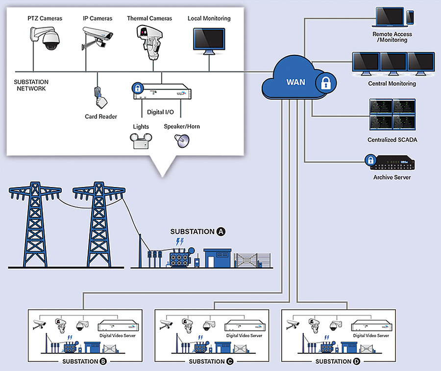
Distributed architecture processes and stores the video at the substation to improve reliability.
(click to enlarge)
Integration With Other Systems
The video system can be integrated with other physical security systems such as access control, lights, sirens etc. The motion detection of the cameras can be linked with lights and sirens to let intruders know that their presence has been detected. This may be enough of a warning to deter the intruders from causing damage or theft at the substation. The notification of the alarm should also be sent to the control center security and operations either into the email system or directly into SCADA.
Utilities may require personnel to notify the control center when they are on site or they will have a credentials-based access control system at the remote site. A video system will provide visual confirmation and identification of personnel on site. The video system can be linked to an access control system to automatically record personnel entering and exiting the site and ensure that proper security and safety procedures are being followed. If the notification to enter the site is done by radio or phone the control center can visually confirm and record the personnel entering the site.
The video system may also be linked to other monitoring systems such as visual or thermal asset monitoring. This can allow the utility to leverage some of the installed infrastructure to run other monitoring systems.
Conclusion
A video system is a key component of an overall physical security plan; however, there are many things to consider when purchasing and installing the system in a substation. The main goal should be to install a system that is reliable, while providing the monitoring features that are required by the utility and the regulating authorities. Equipment with certifications from recognized industry bodies will provide utilities with assurance that the system will operate reliably in a substation environment. Ensuring that the system is secured inside the utility network firewall will prevent tampering and cyber attacks on the system.
About the Author
 Richard Harada heads the product management team at Systems With Intelligence and has more than 20 years of experience in industrial networking communications and applications. Harada has previous work experience at RuggedCom and Siemens Canada, where he was focused on product management for communications in the electric power market. Harada is an electronic engineering technologist and has a Bachelor of Science in computer science from York University in Toronto.