
Understanding diagnostic testing of HV Circuit Breakers is essential. When diagnostic tests are performed on HV Circuit Breakers, valuable information can be extracted. From a technical maintenance perspective, these diagnostic tests provide critical information about the condition of the HV Circuit Breakers.
Standard field tests widely applied today in HV Circuit Breaker diagnostics include:
- Timing and Travel
- Contact Resistance (Static and Dynamic)
- Coil and Motor Current Signatures
- Minimum Pick-Up
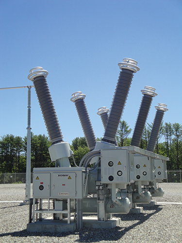
Circuit breaker technology varies depending on the application. Also, the preferred technology is dependent on the geographical region in which it is applied. Case in point, Dead Tank SF6 Filled Circuit Breakers and Bulk Oil Circuit Breakers are primarily used in North America in HV applications, while the rest of the world prefers Live Tank Circuit Breaker technology.
Overall, circuit breakers, regardless of type and technology, are designed with the following three functions in mind:
- Direct current flow between desired sections of an electric power system
- Interrupt current flow under abnormal power system events and conditions, such as faults
- Carry load current under normal power system conditions with minimal losses
These three functions must be performed under both normal and abnormal (fault) conditions, and must perform under strict performance specifications.
Circuit breakers vary by subsystems:
- Insulation System
- Arc Quenching Method
- Mechanism
- Contact Technology
- Control Circuit Schemes
These subsystems need to be analyzed both separately and as a complete electro-mechanical system.
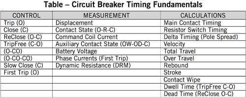
Timing and Travel
Circuit breaker timing and travel measurements entail three steps:
- Perform a dynamic timing and travel measurement
- Calculate performance characteristics
- Compare results to the manufacturer’s recommendations or user-defined limits
Table 4 provides the fundamentals tests and calculations involved in circuit breaker timing measurements and diagnostics.
Contact Resistance (Static and Dynamic)
Contact Resistance can be a complicated subject. Contact assemblies can consist of both main and arcing contact components. To see both main and arcing contact components, the Contact Resistance is analyzed, both statically and dynamically, respectively.
A static contact measurement is to be performed on each phase, using a DC current source. Typical measurements are less than 100 μΩ; however, the manufacturer’s literature should be used to determine the actual expected value. Considering all breaker types, experience has shown measurements range from 10 μΩ _to 150 μΩ _depending on the type, with low voltage vacuum breakers associated with very low measurements, and higher voltage SF6 Dead Tank Breakers producing the higher measurements. It is recommended that at least 100A DC is injected for this test. Also it should be noted that if the breaker is equipped with CTs, it may take several seconds to saturate the opposing effects. Precautions should be taken to ensure that the injected high primary current does not affect protection circuits.
The dynamic resistance measurement is a diagnostic tool to assess the condition of the arcing contacts in SF6 nozzle style interrupters. By measuring the current, voltage, and displacement associated with the contact assembly, it is possible to determine the wear level and integrity of the arcing contact. This measurement, like the static contact resistance measurement, requires high current injection to be successful. Common practice is to use at least 100A DC.
Coil and Motor Current Signatures
Command Coil Signatures – By analyzing the command coil signatures, information regarding lubrication, electrical coil performance and latch operation can be extracted. Lubrication problems are easiest to identify in this scenario. As the armature of the command moves, an expected command coil signature is generated.
Motor Current Signatures – The behavior of motor current shows you the power needed and how it is consumed by the motor. Unusual current levels and motor timing indicate potential electrical fault in the motor.
Minimum Pick-Up
The minimum pick-up measurement is performed to determine the minimum command coil (trip or close) voltage required to operate the circuit breaker. This is the minimum energy needed for the command coil to release the “latch.” The latch can either be a mechanical release mechanism or a value used to control a pneumatic or hydraulic system.
This test is done for each control coil of a circuit breaker. Different considerations must be given to “ganged” versus independent pole operation (IPO) circuit breakers. The test needs to be done for all command coils independently. The IPO breaker may require several more tests to include all command coils.
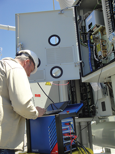
Optimized Toolset
Modern diagnostic test instruments need to be more than just data acquisition systems. The circuit breaker toolset must include not only measurement capabilities, but also an advanced power source. This power source is needed for contact resistance and minimum pick-up. What’s more, by having this power source, this will also provide power to control circuits, coils and motors, when substation power is unavailable.
The diagnostic circuit breaker toolset must provide three functions:
- Timing and Travel Analyzer
- μ-Ohm Meter (Contact Resistance)
- Advanced Power Supply
Therefore, the functions will provide the ability for performing the following tests:
- Timing and Travel
- Contact Resistance (Static and Dynamic)
- Coil and Motor Current Signatures
- Minimum Pick-Up
About the Author
 Charles Sweetser received a B.S. in electrical engineering in 1992 and an M.S. in electrical engineering in 1996 from the University of Maine. He joined OMICRON electronics Corp USA, in 2009, where he presently holds the position of PRIM engineering services manager for North America. Prior to joining OMICRON, he worked 13 years in the electrical apparatus diagnostic and consulting business. He has published several technical papers for IEEE and other industry forums. As a member of IEEE Power & Energy Society (PES) for 15 years, he actively participates in the IEEE Transformers Committee, where he held the position of chair of the FRA Working Group PC57.149 until publication in March 2013. He is also a member of several other working groups and subcommittees. Additional interests include condition assessment of power apparatus and partial discharge.