ALSTOM, a long-term and highlyrespected global supplier in the power generation, transmission and distribution, as well as in the transportation and marine industries, now offers an even broader range of products, services and unique retrofit solutions for power plant generator and auxiliary equipment. Three ALSTOM sectors, Power, T&D and Power Conversion, are able to respond to customer power generation and associated equipment specifications and to provide a broad range of standard and engineered solutions and turnkey services.
ALSTOM equipment ranges from a basic digital AVR and generator protection, to primary power plant generation equipment rated at many hundreds of MVA. A power plant single line diagram can be turned into reality with the supply of hydro, gas and steam turbine power plant prime movers as well as synchronous generators. The basic power plant generation equipment scope of supply may also include high voltage transmission equipment – power transformers, AIS and GIS switchgear – as well as medium and low voltage distribution switchgear. The complete transmission and distribution equipment control can be fully integrated into one of ALSTOM DCS platforms to provide full local and remote control and protection to IEEE standards.
In recent years, there has been a steady growth of retrofit and life extension projects in North America driven by both private sector industry and utility investment project upgrades. There is an increasing demand to upgrade primary power plant generation control equipment especially in the fields of generator protection and excitation, with the added benefits of DCS platforms that can not only integrate ALSTOM equipment but also third party IEDs using object modelling based software systems.
Retrofit of power generation equipment requires careful attention to the original equipment design criteria. Specific areas such as fault levels and generator nameplate details require exact validation. In some instances, nameplates may have been changed during previous upgrades or simply do not even reflect the original design data, resulting in possible site performance testing requirements to determine true equipment ratings and values.
For many decades, the traditional approach to generator protection and excitation was based on electromechanical and analogue devices. Today, the digital world offers a vast array of protection and control devices or IEDs. ALSTOM has recently developed a complete third generation range of numerical protection and control relay IEDs referred to as Micom. Multiple protocol DCS platforms, such as S10, S20, PSCN3020 and Odyssey, are able to integrate the latest ALSTOM and third party IEDs including ALSTOM energy management system equipment. Numerical relays such as Micom offer both IEEE and IEC based multiple generator protection functions, all integrated into one discrete device or relay case.
The integrated generator protection package approach achieves a significant cost reduction and high reliability, compared to using dedicated protection devices for each IEEE function. This is also true for the generator excitation equipment, where a new technology has reduced the number of AVR control and protection devices and function blocks down to either single controller or PLC unit. Digital generator excitation equipment and associated thyristor convertor bridges offer dc field currents ranging from as little as 1 to 6000 amps dc. Generator excitation equipment can be configured to provide half and fully controlled operation of power generator static and rotating exciters.
The protection and control relay IEDs in conjunction with generator excitation equipment can be customised to any installation, using either dedicated hardware- and software-based AVR controllers or a more flexible approach using PLC based AVR equipment. The synergy between generator protection and generator excitation hardware and software and the relative device count reduction offers significant cost, maintenance and streamlining benefits to the user. It is now customary to supply generator control, excitation and protection equipment in one or two control panels, replacing installations that previously required multiple line-up and walk-in panel configurations.
User Interface
The front panel user interface comprises:
A lower cover concealing the front RS232 port, down load/monitor port and battery compartment. The front of the cover can display the name of the product or any user defined name.
Facility for fitting a security lead seal.
Strength comes with flexibility
ALSTOM Micom protection and control relay IED range offers feeder, motor, transformer, generator and line distance protection including specialised functions, such as power quality and generator interconnection protection for distributed power generation. The Micom product range is the achievement of many years of incremental engineering research and development in the field of protection and control engineering originally starting with product ranges such as K, L, M, P and T series.
Micom protection offers multiple features such as:
Comprehensive windows based S1V2 software providing:
Relay set-point programming and fault interrogation of Micom and K relays can either be direct at the relay LCD or from a laptop PC. Programming is based on the use of simple menu driven numerical values associated with the specific protection function and enable/ disable commands. For example, the IEEE overcurrent 51 functions can be disabled or enabled with the text command of “on/off ” or if selected, set to a numerical value of 100.25 amps in primary or secondary current values, with a choice of IEEE or IEC inverse time trip curves.
Micom setpoint and PSL files can be pre-configured and either sent by telephone modem, internet, etc. and downloaded or saved to disk for future download at site. The default programmes of set-point and PSL files can always be recovered from the relay by a simple upload command. The graphical based PSL can also be used to allow external inputs, for example existing electromechanical relays contacts, which can be transferred into any of the Micom relays to allow tripping and time and date stamping as a pass through using a Micom relay.
Retrofitting of any generator with new protection and excitation equipment does achieve a return on investment in terms of maintenance, simplicity and reliability. In the case of generator excitation equipment, there may be a number of considerations to take into account to arrive at the most suitable and cost effective solution that will satisfy local plant and connection utility standards such as:
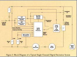
Block Diagram of a Typical Single Channel Digital Excitation System
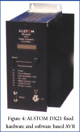
ALSTOM also manufactures a complete range of analogue excitation equipment as well as dedicated hardware- and software-based digital AVRs. However, the RVD PLC AVR stands out as one of the most cost effective and convenient solutions in addressing the above requirements and in cases where great flexibility or possible future control circuit additions may be required.
ALSTOM’s experience with large thyristor convertor bridge power equipment, can also accommodate varying applications. For example, in cases where the user want to retain the existing thyristor convertor bridges and only upgrade the AVR and controls, a complete range of thyristor firing circuit boards is available for this purpose.
Block Diagram of a Typical Single Channel Digital Excitation System
ALSTOM uses a conventional ladder logic programming approach from a laptop PC to pre-set dedicated PLC subroutines for each AVR control loop and protection function. The control loops and protection functions are originally based on the philosophy of the well-established ZVA analogue system. In fixed hardware and software platform AVRs, programming is much the same as for Micom protection relay IEDs, using both numerical units and text commands, with local and remote communication link capability. ALSTOM provides fully tested generator protection and excitation control panels or alternatively, schemes can be engineered for loose equipment supplied for directly mounting into existing panels or equipment.
For more information on ALSTOM generator control, excitation and protection and associated transmission and distribution equipment, search the web on www.alstom.com or contact your local representative.
ALSTOM equipment ranges from a basic digital AVR and generator protection, to primary power plant generation equipment rated at many hundreds of MVA. A power plant single line diagram can be turned into reality with the supply of hydro, gas and steam turbine power plant prime movers as well as synchronous generators. The basic power plant generation equipment scope of supply may also include high voltage transmission equipment – power transformers, AIS and GIS switchgear – as well as medium and low voltage distribution switchgear. The complete transmission and distribution equipment control can be fully integrated into one of ALSTOM DCS platforms to provide full local and remote control and protection to IEEE standards.
In recent years, there has been a steady growth of retrofit and life extension projects in North America driven by both private sector industry and utility investment project upgrades. There is an increasing demand to upgrade primary power plant generation control equipment especially in the fields of generator protection and excitation, with the added benefits of DCS platforms that can not only integrate ALSTOM equipment but also third party IEDs using object modelling based software systems.
Retrofit of power generation equipment requires careful attention to the original equipment design criteria. Specific areas such as fault levels and generator nameplate details require exact validation. In some instances, nameplates may have been changed during previous upgrades or simply do not even reflect the original design data, resulting in possible site performance testing requirements to determine true equipment ratings and values.
For many decades, the traditional approach to generator protection and excitation was based on electromechanical and analogue devices. Today, the digital world offers a vast array of protection and control devices or IEDs. ALSTOM has recently developed a complete third generation range of numerical protection and control relay IEDs referred to as Micom. Multiple protocol DCS platforms, such as S10, S20, PSCN3020 and Odyssey, are able to integrate the latest ALSTOM and third party IEDs including ALSTOM energy management system equipment. Numerical relays such as Micom offer both IEEE and IEC based multiple generator protection functions, all integrated into one discrete device or relay case.
The integrated generator protection package approach achieves a significant cost reduction and high reliability, compared to using dedicated protection devices for each IEEE function. This is also true for the generator excitation equipment, where a new technology has reduced the number of AVR control and protection devices and function blocks down to either single controller or PLC unit. Digital generator excitation equipment and associated thyristor convertor bridges offer dc field currents ranging from as little as 1 to 6000 amps dc. Generator excitation equipment can be configured to provide half and fully controlled operation of power generator static and rotating exciters.
The protection and control relay IEDs in conjunction with generator excitation equipment can be customised to any installation, using either dedicated hardware- and software-based AVR controllers or a more flexible approach using PLC based AVR equipment. The synergy between generator protection and generator excitation hardware and software and the relative device count reduction offers significant cost, maintenance and streamlining benefits to the user. It is now customary to supply generator control, excitation and protection equipment in one or two control panels, replacing installations that previously required multiple line-up and walk-in panel configurations.
User Interface

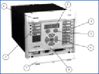
Figure 1: ALSTOM Micom P343 integrated generator protection relay offers more than thirty direct protection functions.
The front panel user interface comprises:
- A 2 X 16 character back-lit liquid crystal display.
- Four fixed function LEDs.
- Eight user programmable LEDs.
- Menu navigation and data entry keys.
- “READ” and “CLEAR” C keys for viewing and acknowledging alarms.
- An upper cover identifying the product name. The cover may be raised to provide access to the product model number, serial number and ratings.
A lower cover concealing the front RS232 port, down load/monitor port and battery compartment. The front of the cover can display the name of the product or any user defined name.
Facility for fitting a security lead seal.
Strength comes with flexibility

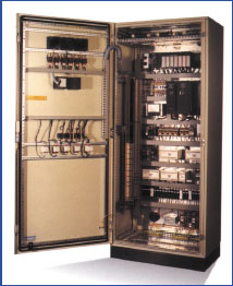
Figure 2: ALSTOM RVD PLC AVR cubicle offers PLC processor auto and processor manual control with additional independent hardwired standby manual backup as well as generator protection.
ALSTOM Micom protection and control relay IED range offers feeder, motor, transformer, generator and line distance protection including specialised functions, such as power quality and generator interconnection protection for distributed power generation. The Micom product range is the achievement of many years of incremental engineering research and development in the field of protection and control engineering originally starting with product ranges such as K, L, M, P and T series.
Micom protection offers multiple features such as:
Comprehensive windows based S1V2 software providing:
- Dual powered versions;
- Fiber optic CT and VT input capability to the IEEE/IEC digital transmission standard;
- Flash memory, to allow relay firm ware and upgrades;
- Multiple opto coupled logic inputs for relay control and blocking techniques;
- Multiple form A and form C relay outputs for sequential and distributed power plant tripping;
- Multiple setting groups;
- Multiple languages;
- Multiple communication port access and protocol choices such as RS232, RS485 and direct fiber with complete DCS capability using S10, S20, S100, PSCN and Odyssey software systems and ethernet LAN topologies;
- Oscillography waveform capture of analogue and digital input and outputs;
- Power system metering;
- Programmable scheme logic using a graphical based drag/drop function block symbol technique for final configuration of the relay logic inputs and relay outputs and digital data base ddb signals;
- Self powered versions;
- Setpoint file programming;
- Text customised editing and of LCD display windows;
- Text based event and fault value recording.
Relay set-point programming and fault interrogation of Micom and K relays can either be direct at the relay LCD or from a laptop PC. Programming is based on the use of simple menu driven numerical values associated with the specific protection function and enable/ disable commands. For example, the IEEE overcurrent 51 functions can be disabled or enabled with the text command of “on/off ” or if selected, set to a numerical value of 100.25 amps in primary or secondary current values, with a choice of IEEE or IEC inverse time trip curves.
Micom setpoint and PSL files can be pre-configured and either sent by telephone modem, internet, etc. and downloaded or saved to disk for future download at site. The default programmes of set-point and PSL files can always be recovered from the relay by a simple upload command. The graphical based PSL can also be used to allow external inputs, for example existing electromechanical relays contacts, which can be transferred into any of the Micom relays to allow tripping and time and date stamping as a pass through using a Micom relay.
Retrofitting of any generator with new protection and excitation equipment does achieve a return on investment in terms of maintenance, simplicity and reliability. In the case of generator excitation equipment, there may be a number of considerations to take into account to arrive at the most suitable and cost effective solution that will satisfy local plant and connection utility standards such as:
- Conversion from rotary excitation to static excitation – the benefits in overall power plant response to transmission system transients and voltage stability;
- Excitation power transformer sizing for field forcing and depressed ac input voltage conditions;
- Field flashing equipment and black start capability requirements;
- Power factor control and VAR control;
- Power system stabilising requirements with reference to North American standards and recommendations;
- Single or dual thyristor convertor bridge – the benefits of redundancy;
- Single or dual processors – the benefits of control loop redundancy and hot standby;
- Short circuit maintenance and implementation methods;
- Thyristor convertor bridge rating available from 1amp to 6000 amps - adequately sizing for field forcing and the use of half and fully controlled bridges;
- Under and over excitation limit control and protection.
Block Diagram of a Typical Single Channel Digital Excitation System

ALSTOM also manufactures a complete range of analogue excitation equipment as well as dedicated hardware- and software-based digital AVRs. However, the RVD PLC AVR stands out as one of the most cost effective and convenient solutions in addressing the above requirements and in cases where great flexibility or possible future control circuit additions may be required.
ALSTOM’s experience with large thyristor convertor bridge power equipment, can also accommodate varying applications. For example, in cases where the user want to retain the existing thyristor convertor bridges and only upgrade the AVR and controls, a complete range of thyristor firing circuit boards is available for this purpose.
Block Diagram of a Typical Single Channel Digital Excitation System

ALSTOM uses a conventional ladder logic programming approach from a laptop PC to pre-set dedicated PLC subroutines for each AVR control loop and protection function. The control loops and protection functions are originally based on the philosophy of the well-established ZVA analogue system. In fixed hardware and software platform AVRs, programming is much the same as for Micom protection relay IEDs, using both numerical units and text commands, with local and remote communication link capability. ALSTOM provides fully tested generator protection and excitation control panels or alternatively, schemes can be engineered for loose equipment supplied for directly mounting into existing panels or equipment.
For more information on ALSTOM generator control, excitation and protection and associated transmission and distribution equipment, search the web on www.alstom.com or contact your local representative.


