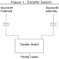
 Medium Voltage Static Transfer Switches (MVSTS) and Medium Voltage Mechanical Transfer Switches (MVATS) perform a common function. They each select between two independent sources of power and switch between the two sources to provide uninterrupted power to the loads. While they perform the same function, the method by which they perform their intended function is different and this method directly impacts the sources and connected load. The basic function is identified in Figure 1.
 All discussions and analysis made in this paper will be based on a key assumption; that no paralleling between the utility sources is allowed.
Mechanical Transfer
Mechanical transfer switches use circuit breakers or switches to perform their transfer function. These mechanical devices can be motor operated air draw-out breakers, solenoid operated vacuum or gas breakers, motor driven switches, etc. In all cases, the isolation between the sources is achieved through the use of open contacts. The operation of these switches depends on an open transition to the source and load. The mechanical switches do not provide a continuous source of power to the loads. During the switching transition there is an interruption of at least 1 1/2 cycles to the connected loads.
Static Transfer
Static transfer switches use solid-state devices, thyristors (SCR) to perform their transfer function. These solid-state devices replace the mechanical operators in the mechanical transfer switches. In lieu of an open transition air break for isolation, the solid-state switches use the high reverse voltage blocking capability of the solid-state devices to control the loads. These switches provide a closed transition to the loads without actually connecting the two sources in parallel. The control algorithm can control the actual switching characteristics and switch response to achieve this result.
Description Of Transfer Operations
There are two approaches that can be taken with transfer equipment open transition or closed transition.
Open Transition
An open transition is a break-before-make operation where the current to the load is interrupted for a brief period of time. This has the advantage of never paralleling the two sources. Non-paralleling of the sources offers several advantages and several potential problems:
| Advantages | Disadvantages |
|
|
Closed Transition
A closed transition is a make-before-break operation where the current to the load is not interrupted during the transfer. This has the advantage constantly supplying the load. Paralleling of the sources offers several advantages and several potential problems:
| Advantages | Disadvantages |
|
|
Applications
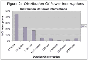
There are many types of applications in which an MVSTS can be compared to an MVATS; normal switching between utility sources, normal to back-up emergency, paralleling, etc. The most common application is as a transfer switch between two utility sources. A study by the Electrical Power Research Institute (EPRI) has provided some data on durations of outages and is presented in Figure 2. This data is based on 600 Site-Months of data at 88 locations. It must be pointed out that this data represents outages only. Utilities do not normally record events such as sags and surges. A utility definition of a problem is usually a lack of voltage, not a reduction. Often utilities do not concern themselves if the voltage is within 10% - 20%. But even a 10% reduction for a few cycles can impact many operations. Based on outage data alone, 45% of outages will not allow most mechanical transfer switches to respond and 80% of the unplanned outages will not allow the slower backup generation to start and come up to speed. According to the National Power Laboratory Study, 1990 – Present, interruptions are only a tiny portion of the overall power quality concern.
| Table 1: Power Quality Events | ||
| PQ Event | Occurrence | Comments |
| Voltage Sag | 60% | >20% Below Nominal RMS |
| Voltage Swell | 29% | 6% - 27% Overvoltage |
| Impulses/Spikes | 8% | 0V RMS > 4 mSec |
| Interruptions | 3% | 100V Above Sinewave Peak |
Table 1 shows that the utility may be aware of only 3% of the total power quality problem. However, these relatively short and unreported disturbances are the primary cause of critical equipment disruptions. The result is that, while the critical plant systems can be maintained via distributed UPS installations, the non-critical systems are not and can clearly impact production. “Non-Critical” functions such as high efficiency lighting may take minutes to come back on. UPS installations are not cheap and they require maintenance for their batteries.
The MVSTS excels in the application where two, relatively independent, utility sources are available. Relatively independent sources require that problems experienced on one source are not seen on the other source. Both sources are also required to be able to support the entire facility load. Data compiled from MVSTS users has determined that most problems experienced on utility services are at the distribution level not the transmission level. This data appears in Table 2 from a study conducted at four MVSTS locations between 11/96 and 9/98.
Table 1 indicates that 3% of utility events occur on the transmission portion of a utility system and is supported by Table 2. What does this mean regarding the application of the MVSTS? If the two substations share a common transmission line, according to Table 2, there is a 3% chance of both subs being impacted by a transmission event on the common transmission line. Assuming that the utility offers typical 4 9’s availability (99.99%), the MVSTS will protect against 97% of the events in the 99.99% availability range. This provides a power availability of 99.9997% from two subs sharing a common transmission line. Two independent transmission lines of 99.99% each will provide even higher power availability. A local utility reports that there exists a 1:2000 chance of an interruption on a transmission line and a 1:3,000,000 of two independent transmission lines failing simultaneously. Given the reliability and availability of utility sources, utilizing an MVSTS in lieu of backup generation or UPS is a very feasible and cost effective solution.
| Table 2: Transmission vs. Distribution Events (Actual Installations in North America) | ||
| Location | Distribution Events | Transmission Events |
| Front Street (9/95 - 9/98) | 27 | 0 |
| CONDEA Vista (9/96 - 9/98) | 19 | 0 |
| Ford Motor Co (11/96 - 11/97) | 15 | 1 |
| FMC Corp (5/98 – 9/98) | 16 | 1 |
| Total | 77 | 2 |
Other considerations concerning the application of the MVSTS are:
- There are no environmental considerations as with a backup generation source or UPS batteries:
- Fuel, Noise, Air Quality.
- Limited run-backup time due to environmental restrictions.
- No battery disposal issues.
- The response is much faster:
- The MVSTS can respond in sub cycles vs. seconds for the generator.
- The MVSTS can respond in sub cycles vs. cycles for the MVATS for outages. The MVATS response to sags and swells is much longer, up to several seconds.
- Reduced maintenance:
- Backup generation requires periodic maintenance.
- Test starts and runs (normally quarterly) of the backup generator are required and count towards the total hours allowed by the permits.
- UPS require quarterly battery maintenance and periodic battery disposal.
- The MVATS depends on mechanical operators and must be maintained.
- The MVSTS has few moving parts; the bypass switches and cooling fans. Operation of the bypass switches is not required for successful operation of the MVSTS. The MVSTS bypass switches are for maintenance only.
- Rotary UPS requires mechanical maintenance as well as backup diesel maintenance, if a backup diesel is included for long-term protection.
- Reduced Cost, based on 5kV, 5MVA installation.
- Not impacted by the fluctuating cost of fuels.
- UPS initial costs can 2-3 times that of a MVSTS.
- UPS batteries require maintenance and replacement; MVSTS life is in excess of 30 years.
- A 5kV 5MVA backup generator can be 3X – 5X the cost of a MVSTS depending on fuel and auxiliary switchgear.
- Rotary UPS provides limited ride thru only, seconds to several minutes depending on load. Longer-term backup requires a back up long term source such as a diesel generator.
| Table 3: Equipment Cost Of Power Quality Solutions vs. MVSTS | ||||
| MVSTS | MVATS | Backup Gen. | UPS | Rotary UPS |
| $=1.0X | $=0.4X - 0.7X | $=3X - 5X | $=4X – 5X | $=7X – 10X |
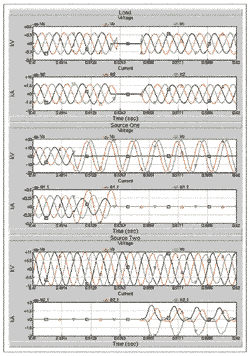
Figure 3: 1 1/2 Cycle MVATS Transfer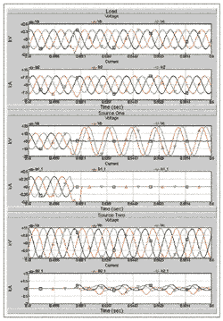
Figure 4: 1/4 Cycle MVSTS Transfer
Table 3 summarizes the equipment costs for an MVSTS, MVATS, UPS, Rotary UPS with backup generator (Rotary/Gen Set) and backup generator. Assume a 5kV, 5MVA installation.
The backup generation requires the installation of two 2.5MVA units with the associated controls and synchronizing equipment. The UPS requires 10-500KVA units with a battery of only 10 minutes duration. The Rotary UPS cost includes a backup diesel generator for long-term backup. The Rotary UPS is limited to only a few minutes of power backup without a diesel. All of these installations are maintenance intensive as well. The costs in Table 3 also do not allow for redundancy or over-capacity to serve as a backup. The MVSTS provides a backup capability inherent in its design. The MVSTS controller constantly performs self-diagnostics. In the event of a problem being detected, the controller will annunciate the proper warning and take appropriate action. This allows the system user to perform the proper corrective maintenance in a timely manner. It is not always possible to determine the status of a backup generator or a MVATS. If the MVSTS problem will not allow the STS portion of the MVSTS to operate, the STS is automatically isolated via the auxiliary mechanical switchgear. This auxiliary switchgear also provides backup capability to the MVSTS installation by acting as an MVATS.
An MVATS installation does have one advantage over a MVSTS; the cost of a MVATS can be lower. A typical MVATS can be as much as
40% – 70% of the cost of a MVSTS. The problem with the MVATS is the response time, or more specifically, the lack of response time. Using fast switch technology the response time can be greatly reduced but these are still mechanical operators and subject to environmental and maintenance issues. The local utility exercises control over what is installed at the service entrance. This includes the type of equipment and the settings. The local utility does not want large numbers of open transition transfers to occur since this will generate voltage sages and surges with every transfer. To prevent this from happening, the utility requires that the voltage settings be set to 80% or even lower before the controls will initiate a transfer. Even the quickest mechanical transfer system has an open transition period of 1 1/2 cycles, not counting the detection time and mechanical response for the first switch to open.
The MVSTS response is fast enough, 1/4 cycle nominal, such that the loads do not momentarily shutdown and there is no magnetizing in-rush. The utility sees a much-reduced switching event. Since the voltage event is reduced, the utility will allow the settings on the switch to be set much higher then a mechanical switch. Normal settings for a MVSTS would be on the order of a 5% – 10% voltage reduction with detection and transfer time of 1/4 cycle nominal. Clearly, the MVSTS offers the performance of a UPS at a much-reduced acquisition, installation, and maintenance cost. This response is summarized in Figures 3 and 4. These figures simulate (using PSCAD Software) and compare the impact of a 1/4 cycle MVSTS to a MVMTS with a 1 1/2–cycle response. Source 1 and Source 2 show the voltage and current at the input to the switch, Load shows the secondary values of voltage and current at the customer loads. Figure 3 shows the switching event with a mechanical switch having a 1 1/2 cycle open transition. Figure 4 shows the same switching with a static switch having a 1/4 cycle transition. The most obvious effect of the 1 1/2 cycle mechanical transfer is that the load voltage and current have been interrupted. This results in a large in-rush into the primary of the load transformer, shown in the Source 2 current, on the order of 12X full load current. The 1/4 cycle STS does not show this type of in-rush. The in-rush for the 1/4 cycle STS is on the order of 2X–3X and has minimal impact on the secondary voltage and current.
Table 4: Summary Comparison of Power Quality Options
Table 4: Summary Comparison of Power Quality Options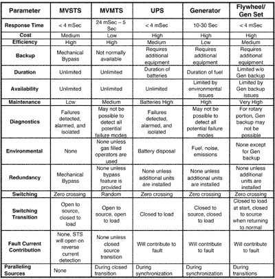
Summary
The MVSTS can be incorporated into many applications. It can work in conjunction with backup sources such as generators and/or UPS systems. The MVSTS can also replace these systems as a lower cost solution. The reliability of the MVSTS is very high, the Mean Time Between Critical Failure (MTBCF) is calculated to be 23+ years. The MVSTS also outperforms the MVATS with regards to transfer speed. While the controls of both the mechanical and static switches sense the anomaly in the same sub-cycle time frame, only the MVSTS can react in the same sub-cycle time frame. This is done without paralleling of the two sources. The connected load is supplied with a source of uninterrupted power while the sources see an open transition.
The design of an MVSTS is such that it can be engineered and designed to fit into existing and future systems and installations. The design is modular so that different switchgear variations and protection arrangements can be used. Circuit breakers can be substituted for the motor operated switches. These breakers can provide the overcurrent 50/51 functions. Load isolation and protection breakers or switches can be added to the switchgear to provide flexibility and isolation.
The advantages and disadvantages of the MVSTS, MVATS, backup generators, and UPS systems previously discussed are summarized for comparison in Table 4. n
About the Author
This article is written to address the concerns of utilities and the end-users of Medium Voltage STS technologies. The concepts discussed, in particular the actual switching and control algorithms, are applicable to Low Voltage STS technologies as well. Silicon Power also provides complete line of low voltage solutions.
William P. Risko, P.E., Sr. Applications Engineer, Silicon Power Corporation
B.S.E.E from Drexel University (1984)
M.E.S from Penn State (1997)


