Abstract: Serial communications has been the mainstay for communication systems for more than a decade using RS232 and RS485 as the physical layer. However, the Ethernet juggernaut is enticing systems engineers to re-evaluate their existing approach to telemetry with the potential benefits of a bigger ‘pipe’. Fortunately, familiar protocols support TCP/IP over Ethernet making the switch relatively easy for greenfield deployments. Retrofitting Ethernet and newer IEDs into existing communications systems require supporting a hybrid network of both Ethernet and serial devices. One approach to a hybrid network is serial tunnelling through serial servers as described below and includes an example illustrating the benefits of a real implementation.
Ethernet Brief History
Today Ethernet is the predominant and most popular networking technology used in office and home environments. Their use is quickly becoming popular for industrial and utility applications including substation automation networks.
Ethernet networks were not developed with the intention of being used in substations and other harsh environments. New Ethernet equipment has been designed to operate under extreme harsh environment; therefore, both industrial and utility networking experts are moving forward accepting the limitations of Ethernet networks and solving the associated problems, with the sole objective of taking advantage of the benefits provided by Ethernet.
Ethernet in Substation Environment
If Ethernet devices are used in substation automation applications, they should comply with either IEC 61850-3 or IEEE P1613 standards for EMI immunity and environmental requirements to ensure reliable operation of networking equipment in substation environments.
For applications where the Ethernet network will be involved in critical protection functions, the Ethernet switches should comply with the Class 2 device definition given in IEEE P1613 (i.e. error free communications during the application EMI immunity type tests).
Managed Ethernet switches with advanced Layer 2 and Layer 3 features such as IEEE 802.3 Full-Duplex operation (no collisions), IEEE 802.1p Priority Queuing, IEEE 802.1Q VLAN, IEEE 802.1w Rapid Spanning Tree and IGMP Snooping / Multicast Filtering should be used to ensure real-time deterministic performance.
A variety of flexible network architectures offering different levels of performance, cost and redundancy are achievable using managed Ethernet switches.
The following are a few reasons why migrating to Ethernet is the way of the future in Substation Automation:
• Enables Peer-to-Peer Communications
• Allow for Multiple Masters
• Client – Server vs. Master – Slave
• Higher data transfer
• Higher bandwidth
• Fast Network Recovery protocols
Enabling Peer-to-Peer Communications
Peer-to-peer communication allows two or more protection and control relays to share information, enabling the potential for extremely fast system reconfiguration, enhanced protection and improved reliability. Typical applications being deployed include protection pilot schemes, relay cross-tripping, distributed source transfer schemes and bus differential protection.
As previously noted, Ethernet as a media has been mentioned a number of times and installing Ethernet-based LANs in substations is a growing trend.
Peer-to-peer protection and control systems implemented over Ethernet addresses the available bandwidth problem that can occur with peer-to-peer protocols such as GOOSE messaging, part of the UCA 2.0/IEC 61850 standards.
Some relay manufacturers have developed their own proprietary peer-to-peer communications protocol originally designed to work over serial networks with operating speeds as expected for the application.
The fact that not all relay vendors choose to follow international standards force end users to search for ways to allow the co-existence of serial and Ethernet systems in the same network, eliminating the need to build and maintain two or more separate networks.
SERIAL TO ETHERNET TECHNOLOGIES
Overview
Ethernet infrastructure is usually available, or can be easily implemented. Buildings tend to have existing Ethernet networks. PLC and RTU manufacturers are starting to develop Ethernet add-ons to network their products, at a premium cost for this functionality. Serial servers are a cost effective solution that, utilizing Serial-to-Ethernet technology, allow integrating serial devices that are not Ethernet capable together with Ethernet capable devices on the same local area network (LAN).
A transparent serial tunnel is created over Ethernet without changing much of the existing setup. The ability to create Virtual COM Ports eliminates the need to upgrade the existing hardware with network add-on modules.
The main benefits of having access to the substation LAN are:
• High-speed peer-to-peer communications between IEDs
• Reduced inter-IED wiring
• Coexisting multiple protocols on the same physical network
• Fast Network Recovery utilizing protection protocols like eRSTP for more reliability should a link failure occurs.
Over all result is a protected network architecture that provides reliability and high availability with all components integrated on the same Ethernet backbone network at lower cost.
RaW Socket TCP/IP
The basic idea behind Raw Socket is extending a serial network behind serial communications limitations by encapsulating serial data in IP datagrams that can travel over a standard IP network that spans across cities, countries, and some times continents.
Socket mode of operation provides a way of directly accessing device servers across a TCP/IP network without first having to install a driver. Sockets are standard APIs (Application Programming Interfaces) used to access network devices over a TCP/IP network. Two socket API standards are in common use. The original standard, known simply as ‘Sockets’, was developed for the Unix/Linux environment. The Windows alternative is ‘Win Sock’. Although there are fundamental differences between these two standards, most of the API function calls from either system have the same structure and consequently, socket based network control programs are portable across almost all system platforms.
Two appropriately configured device servers can work in unison to form a serial tunnel. The serial tunnel operates by encapsulating serial data in a TCP/IP packet, which is then transported across an Ethernet network. This operation mode allows transparent connection of all serial devices and is also a good way to network DOS based PCs or PDAs, or two serial IEDs connected in a peer-to-peer mode using IEC61850 GOOSE messages or SEL Mirrored Bits®. Because the connection is truly transparent, proprietary protocols can be transmitted.

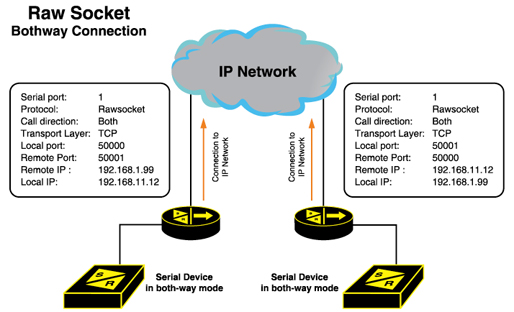
Figure 1 RaW Socket Operation
If the configuration is done as both-way as shown in Figure 1, any of the two sides can start the connection. The remote IP address and remote port are necessary to be configured for scheme to work.
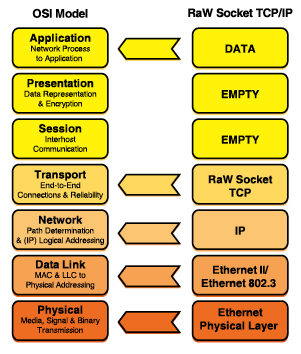
Figure 2 shows the OSI Model applied to RaW Socket serial to Ethernet mode of operation.

Figure 2 OSI Model of RaW Socket TCP/IP
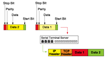
RaW Socket encapsulation will permit encapsulating serial traffic into IP packets. During the encapsulation process a decision will need to be made about when to packetize serial information.
The following options are available on state of the art serial server devices for Raw Socket encapsulation:
• Packetize on receiving a specific character: The server will examine each received character and will packetize and forward upon receiving the specific character. The character is usually a
• Packetize on timeout: The server will wait for a configurable time after receiving a character before packetizing and forwarding. If another character arrives during the waiting interval, the timer is restated. This method allows characters transmitted as a part of an entire message to be forwarded to the network in a single packet, when the timer expires after receiving the very last character of the message.
• Packetize on full packet: The server will always packetize and forward on a full packet, i.e. when the number of characters fills its communications buffer (1K bytes).

Figure 3 RaW Socket Packatization
Comparing Serial with Ethernet Communications
Comparing the characteristics of Serial vs. Ethernet communications, the following are the most important reasons when considering one versus the other:
1. Reliability of Data Communication
The Ethernet is a secure and proven way of data communication with error connection handled by the hardware and the TCP world standard communication protocol.
The primary limiting factor for shared-bus topologies like serial links is that of high I/O and limited distance.
2. Speed of Data communication
Using Ethernet data is moving with a minimum speed of 1 Mbps with absolute error correction compared to RS232 where the speed is at best one tenth of the Ethernet’s minimum, without or minimum error correction.
3. Ethernet Better and Faster Recovery
Ethernet networks utilize redundant links and recovery protocols as protection techniques against link failures.
4. Standardized Cable and Connection
For the Ethernet network the engineer is using world class unshielded twisted pair (UTP) cables and plugs however in the serial world there are no cable standards.
5. Distance of Data Communication and Noise immunity
When using Ethernet technology the data can be error free at high speed of 1mbps minimum over distances up to 50m. When using the RS232 for speeds of 110kbps the theoretical distance for error free communication is relatively very short. This means that in the majority of cases the distance alone between the IED and the PC is a key factor to choose Ethernet over serial communications. Furthermore in noisy environments the Ethernet cable is proven to work while the RS232 or RS485 non standard cables offer no guarantee that may corrupt data.
Serial to Ethernet Migration Example
In the early 1970’s, utilities began deploying communications to substations, in some cases having looped source feeds for the purpose of providing Distance Protection Pilot Schemes such as Permissive Overreach Transfer Trip (POTT) high-speed relaying between the substations.
Early communication circuits used dedicated copper leased circuits as the medium of transportation for the Frequency Shift Keying (FSK) relay equipment. In the late 1990’s, they began installing fiber optic cables between the substations to enhance the relay protection system communications, in some cases utilizing Multiplexers on SONET using channel division at T1 speeds. Both of these methods are still in use today because a cost effective solution may not be available that could be used to retrofit existing configurations without the need to replace the relays to new, more advanced models that support Ethernet communications.
In early 2000’s the need to consolidate substation communications to one common network platform was identified. The main reason for considering a change was simply to take advantage of additional benefits enabled by new technologies such as Ethernet. With time, Ethernet over fiber optics has been selected by many utilities as the medium to provide a communications highway; however, not all the Protection and Control devices currently in service have Ethernet connectivity. As previously stated, Serial Servers are probably the simplest and most economical method to bring serial devices to the local area network.
Once at the Local Area Network level, substation hardened Ethernet switches are also chosen due to their ability to provide a stable solution over fiber at link speeds of up to 1GB. SCADA RTUs, IP-based surveillance cameras, AMI meter collection nodes, protective relay engineering access and oscillography can be moved to the Ethernet network for integrated communications, allowing information to reach other stake holders within the Utility Enterprise.
In many situations, the move to Ethernet does not, however, provide an immediate solution to replace the legacy copper leased circuits for high-speed POTT relaying. Relay vendors choose to use proprietary rather then open protocols which, in most cases, are incompatible with standard serial communications parameters, preventing use of Ethernet for communications. Without an immediate solution to transport such protocols across Ethernet within the relay-required timing parameters, utilities must find methods to use existing relays over an Ethernet communications structure.
As described above, serial servers are used to create an IP tunnel between two serial servers across an Ethernet infrastructure. Once the data transfer is possible through the IP tunnel using the any standard or proprietary protocol over the network, users may find themselves facing timing and data integrity issues.
Since serial servers have proven their ability to transport data between relays, serial servers and relay vendors are working together to enhance their products to accurately transmit proprietary protocols over Ethernet. Bench tests have confirmed the solution to be effective. Initial tests proved that timing performance can be even better than expected, with confirmed data integrity for secure high-speed relay protection.

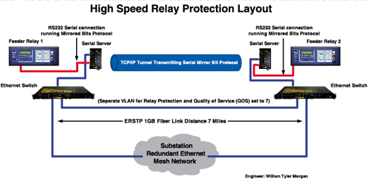
Figure 4 Network Topology
Installed Configuration
In the following example, two feeder relays are been connected back-to-back through a serial server which provides a TCP/IP tunnel or conversion and transport of serial peer-to-peer messages. While having a unique IP address, each serial server has also in records the destination IP address of the adjacent serial server to complete the TCP/IP tunnel.
It is important to note that TCP is recommended over UDP protocol because of the deterministic characteristics of TCP versus the broadcast approach of UDP and its ability to provide secure packet transfers.
The serial servers are connected to Ethernet switches used as the communications backbone between the substations, with 1GB fiber links in a mesh configuration to provide redundancy.
The use of Ethernet technology enables the following features:
• Enhanced Rapid Spanning Tree Protocol (eRSTPTM) dynamically reroutes the network traffic in the event of a fiber break or equipment failure.
• Dedicated VLAN ensures interference-free performance of the high speed relay communications.
• Quality of Service (QoS) gives higher priority to packets containing peer-to-peer messages. The communication circuit performance provided by the serial server has proven to be transparent to the operation of the relays, whether performing under fault conditions or simply monitoring the heartbeat of the companion relay.
Performance Measures
Before: Round trip time of peer-to-peer messages was 160ms (9-10 cycles) using legacy FSK equipment leased lines or the SONET-based Multiplexer.
Lab tests: Round trip time was measured at 40ms (2.5 cycles). The lab test consisted of 2 feeder relays connected back-to-back through 2 serial servers. The serial servers were connected to a standard Ethernet switch with no other network traffic present during the test.
Present: In live production using Ethernet switches between sites over Ethernet at 1GB speeds, the round trip time was less than 30ms (2 cycles) over an approximate ome-way circuit distance of seven miles. The total distance was 14 miles round trip in this installation.
Note: To provide accurate line fault protection, one substation relay must send a request to trip to the other substation relay and receive permission to trip within 9 or 10 cycles.
Conclusion Based upon performance test results, serial servers have proven to be an effective alternative to transport peer-to-peer messages using proprietary protocols between relays over an Ethernet Network. This will replace existing frequency shift keying (FSK) systems over leased lines that provide this service hence reducing the overall operating cost. The main goal of moving substation communications to the fiber Ethernet network has now been achieved.
The Rapid Spanning Tree Protocol feature provided by Ethernet networks can now be used to increase the reliability and availability of data originated from serial devices.
About the Authors
William Tyler Morgan is a Network Engineer II at EPB of Chattanooga TN, which provides electric power to customers in a 600 sq mile+ coverage area along with providing High Speed Internet and Phone Services over fiber optics to businesses. For 20 years, Mr. Morgan has been involved in the design and installation of wired and wireless networks along with installing and supporting of Windows, Novell, UNIX, OS2 and Linux servers operating systems. Prior to joining EPB, Mr. Morgan worked for two network integrators that provided network engineering services. Mr. Morgan has been with EPB for 12 years designing and supporting internal and external networks, supporting multiple server operating systems along with converting all the substation systems to operate over one standardized network infra structure, including Protection and Control, Substation Automation, SCADA and mobilized wireless workforce installed in the EPB support vehicles with real time GPS tracking.
Jason Read is a Senior Engineer at EPB of Chattanooga TN, which provides electric power to customers in a 600 sq mile+ coverage area along with providing High Speed Internet and Phone Services over fiber optics to businesses. For 15 years, Mr. Read has been involved in the design and commissioning of power substations. Prior to joining EPB, Mr. Read worked for 8 years at one of the premier nationwide turnkey solution providers for medium and high voltage electrical systems. Mr. Read has been with EPB for 7 years providing design and substation support for more than 125 substations that EPB operates.
René Midence is the Utility Market Manager of RuggedCom Inc. a leading manufacturer of industrially hardened communications technology for mission-critical applications in harsh environments. For over 25 years, Mr. Midence has been involved in the design and commissioning of power substations and power plants, including Protection and Control, SCADA, Substation Automation and Substation LAN systems. Prior to joining RuggedCom Inc. Mr. Midence worked for GE Multilin over 8 years as Senior Technical Support and Applications Engineer and 2 years as Product Manager responsible for Industrial products. Mr. Midence graduated from the University of Honduras in 1983 with a Bachelor of Applied Science degree in Electrical and Industrial Engineering. Mr. Midence is a member of Institute of Electrical and Electronic Engineers (IEEE) and International Electrotechnical Commission (IEC) TC57 WG10.
EPB is an electric distribution system that purchases 100% of its power from the TVA. EPB provides electric service to more than 168,340 customers in a 600-square-mile service territory encompassing the greater Chattanooga area.


