
1 INTRODUCTION
Existing AC transmission systems are operated with three physically distinct systems of conductors referred to as “phases”, where sinusoidal voltages and currents in each are offset with respect to each other to exploit Nicolas Tesla’s invention of the three-phase alternating-current (AC) generator and motor. A key characteristic is that they are symmetrically operated: if any problem develops on one or more phases, all three are taken out of service. Traditionally, this has been done to avoid the generation of harmful load voltages and currents which can occur when asymmetrical conditions arise.
1.1 SYMMETRIC OPERATION OF POWER TRANSMISSION SYSTEMS
When a fault occurs on either one, two or three phases of a transmission line, circuit breakers at both ends remove all three phases from operation until subsequent human intervention has resolved the situation. This strategy has significant disadvantages:
- 1. operating the three phases as a single organic whole increases the probability of transmission loss: any one phase affects the operation of the other two;
2. a problem with 33% of a three-phase line (the most frequent occurrence) results in the loss of 100% of its capacity;
3. after the fault is cleared, system operators must apply remedial measures, such as modifying generation to redirect power flows so that the system can sustain further contingencies: this exposes operations to potential human error and higher risk.
All of these issues influenced the Northeast U. S. and Canada blackout of August 2003 in one way or another (1).
1.2 ASYMMETRIC OPERATION OF POWER TRANSMISSION SYSTEMS
Asymmetric operation is defined as the operation of a three-phase
transmission line as three independently-operated entities (2). When fault conditions occur, a three-phase line is operated with one or two phases out of service for single-line transmission corridors, or with one, two, or three phases out of service in the case of multiple-line corridors. However, to do so requires achieving three operational objectives:
- a) the faulted corridor appears to operate symmetrically at both extremities;
b) the faulted corridor returns to its pre-contingency electrical state (i.e. impedances, voltages, currents, and power transfer);
c) undesirable voltages and currents are “contained” within the faulted corridor.
Since the post-contingency system is electrically identical to its pre-contingency state, there is no need for immediate operator post-fault remedial measures: they are “built-in” to the strategy (though local intervention is still required to rectify the fault condition)!
For this to occur, compensating equipment must be introduced while faulted phase(s) is(are) switched out by means of circuit breakers. Such equipment can either be conventional, inexpensive passive devices, such as capacitors and reactors equipped with appropriate switching equipment, or more complex, rapid and expensive power-electronic devices such as Flexible AC Transmission System (FACTS) controllers (7,8). Both approaches have their strengths and weaknesses, and the final choice will often depend on system-specific constraints imposed by the system planner.
2 BENEFIT OF ASYMMETRIC OPERATION
2.1 STATISTICS OF TRANSMISSION LINE FAILURES
Most transmission line faults are single-phase (varying from 60% to 97% with increasing voltage level (3,4,6)). However, the three-phase fault – often used concurrently with the subsequent loss of major transmission equipment - has long been the industry norm for establishing system performance under difficult conditions (9), even though three-phase faults have no more than a 1% robability of occurrence. Clearly, the three-phase fault criterion is limited in terms of physical significance, and one can argue that a symmetrical three-phase response is inappropriate up to 97% of the time, depending on voltage. In the past, this criterion served a useful purpose as an umbrella contingency, accounting for lack of knowledge of either operating context or system dynamics. However, asymmetric operation enables power systems to respond surgically to contingencies while maintaining symmetrical capability when required.
2.2 RELIABILITY ANALYSIS
The most frequently used reliability index in transmission planning is the Loss of Load Expectation (LOLE), which is the expected mean of energy not supplied due to the failure of network components (5), quantified in either energy units or dollars. LOLE therefore measures risk. Here, the LOLE is used to compare the risk of operating a single- or multiple-line transmission corridor either symmetrically, or asymmetrically.
Fig. 1 shows the logic circuits for the reliability analysis of a three-phase transmission line under each type of operation. In the symmetrical approach, events leading to the loss of any one phase result in the loss of all three phases. In the asymmetrical approach, the three phases function independently.
Consider a corridor of N three-phase lines transmitting a total power value of T, where the probability of successful transmission of each phase is p. According to (2), the expected mean non-transmitted power under symmetric operation LOLEsym and the expected mean non-transmitted power under asymmetric operation LOLEasym are:
 [1]
[1]where fch is a load factor which takes average load variations into account. An arbitrary load factor between 50% and 75% is typically acceptable.
The difference between the LOLE of symmetric and that of asymmetric operation yields the benefit of asymmetric operation which can be evaluated at the energy generation cost:
 [2]
[2]Clearly, equation [2] is always greater than zero for 0 < p < 1: this means that the risk is always higher under symmetric operation.
Example 1: Asymmetric Operation of a Two-Line 400 kV, 300 km Corridor
The probability of non-transmission can be evaluated as 0.133% per 100 km of line (6). For each phase with an equivalent length of 300 km, one has : q = 0.004 and p = 0.996. The benefit of asymmetric operation is obtained from equation (2) as: ?LOLE = 0.01195 fch T. Assuming a generation cost of 2500 $/kW and a load factor of 75%, the benefit of the asymmetric approach over the symmetric approach is approximately
23 $/kW.
3 IMPLEMENTATION
Two cases must be considered for implementing asymmetric operation: a) the multiple-line corridor and b) the single-line corridor. The following sections focus on the use of conventional devices due to their lower cost.
3.1 MULTIPLE-LINE CORRIDOR
A lossless, uncoupled, lumped-parameter transmission line model is used as a starting point: this simplifies the analysis while leading to a reasonable estimate of the capacity and cost of the compensating equipment.
Compensating Impedances
Consider a corridor of N lines with L individual ai -phases out of service (for N ? 2). The problem is to determine the conditions for which the power transmitted on N ai -phases in symmetric mode is equal to that of N-L compensated remaining ai -phases in asymmetric mode.
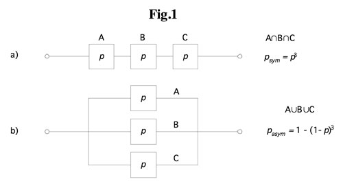

Fig. 2a) shows the equivalent circuit for N parallel ai -phases operated symmetrically. VS and VR are respectively the line-to-line rms voltages of the sending and the receiving ends, and Xp and Bp are respectively the series impedance and the shunt susceptance of each ai -phase. With L ai -phases out of service, the equivalent circuit is shown in Fig. 2b). Xs and BC are, respectively, the series impedance and the shunt susceptance of the compensating devices for each ai -phase, defined as follows:
 [3]
[3]With these compensating elements, the asymmetrically-operated compensated corridor A-phase with L open ai -phases has the same electrical characteristics and carries the same power as the symmetrically-operated corridor A-phase with N operational ai -phases.
Installed Reactive Power
The total installed reactive power for series compensation QTseries is calculated assuming that series-connected reactive power is available to every phase of every line. The total installed series reactive power in the 3N phases of the corridor is:
 [4]
[4]where Ip is the rms value of the current in the equivalent line.
The value of the total installed shunt reactive power QTshunt is calculated based on the fact that any phase of any line can be lost. However, there is no need to compensate for particular ai -phases as shunt compensation can be installed on the sending-end and receiving-end buses. The total reactive power installed for shunt compensation is given by:
 [5]
[5]where VN is the rms phase-to-ground voltage.
Example 2: Two-Line 400 kV, 300 km Corridor with Lossless Lines
Two 400 kV, 300 km, lossless, transposed lines loaded to their surge impedance loading (SIL = 1400 MW) are equipped to sustain the loss of any combination of three different phases in succession, on either of the two three-phase lines. Fig. 3 shows this corridor with one phase out of service. The unit length parameters are xL = 0.3 ?/km and bL = 6.0 µS/km. Thus,
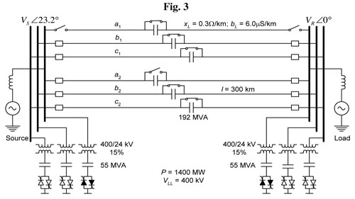
for 300 km, XL = 90 ?, and BL = 1.80x10⁻³ S. For L = 1, a total of 1150 Mvar are required in series compensation, and the total needs for shunt compensation, including 15% for the SVS transformer losses, are 330 Mvar.
3.2 SINGLE-LINE CORRIDOR
The solution to the single-line case requires filters to eliminate undesirable negative and zero sequence currents resulting from a one- or two-phase-open situation. As the single-phase fault has the highest probability of occurrence, the loss of two phases is not considered here.
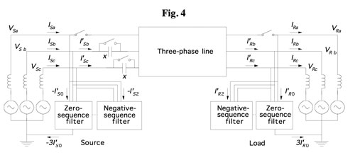
- Fig. 4 illustrates the asymmetric operation of a three-phase line with phase a out of service. During asymmetric operation with one phase open, three basic compensating elements must be introduced to rebalance
voltages and currents:
1. Series compensation of the sound phases (phases b and c in Fig. 4) to lower the series reactance, maintain the same angular spread and ensure the flow of the pre-contingency power;
2. Zero-sequence filters, at each extremity, to afford a low-impedance path for zero sequence current;
3. Negative sequence filters at each extremity to eliminate negative-sequence currents. Depending on the planning criteria, the negative-sequence compensator and zero-sequence filter at each end of the line can be grouped together (2);
Example 3: Asymmetric Operation of a Single-Line 120 kV, 100 km Corridor:
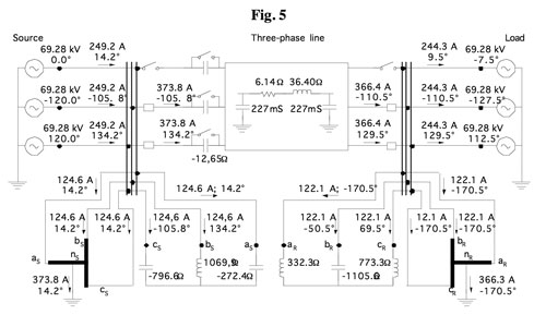
Fig. 5 illustrates a three-phase 120 kV, 100 km line with parameters r = 0.061 ?/km, xL = 0.3644 ?/km, bL = 4.54 x 10⁻⁶ S/km with a phase open. The load power is 50 MW. Compensation of the positive sequence requires three capacitors of 2 Mvar each for a total of 6 Mvar. Compensation of the negative sequence requires 68 Mvar at the ends of the line. Filtering zero sequence requires 16 Mvar.
4 FINANCIAL ANALYSIS
4.1 RETROFIT OF EXISTING CORRIDORS
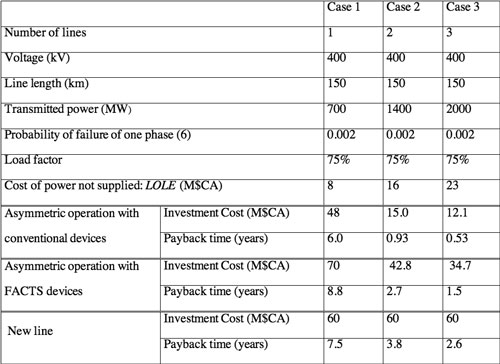
Table 1 summarizes the financial analysis for three 400 kV, 150 km asymmetrically operated corridors having respectively one, two and three transmission lines.
For a single line, the cost of the LOLE (excluding the larger social and economic costs) is lower than the investment cost of asymmetric operation, and much lower than the cost of building a new line: the payback period is therefore greater than one year. For two or three lines, the investment cost of asymmetric operation using conventional devices is lower than the cost of the LOLE, yielding a payback time of less than one year. In other words, part of the investment for asymmetric operation is already present in the case of multiple lines!

4.2 NEW CORRIDORS
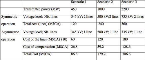
Table 2 identifies three different transmission scenarios under symmetric and asymmetric operation for new transmission capacity. Each scenario compares the cost of a two-line, symmetrically-operated transmission corridor to a single-line, asymmetrically-operated corridor of the same capacity, both respecting an “N-1” criterion (9).
For a symmetrically-operated system, “N-1” represents the loss of a three-phase line; for an asymmetrically-operated system, “N-1” represents the loss of a single phase. The capacities are considered identical as planning criteria consider the immediate post-contingency capacity as the pre-contingency corridor capacity. As the reliability of both cases of each scenario is essentially identical (they respect their respective “N-1” criterion), one must compare them on the basis of investment costs, not risk (i.e., LOLE).
Cost Analysis
Table 3 presents the cost summary based on the use of conventional elements, including rights-of-way. In all three, the cost of a single, asymmetrically-operated 300 km line is less than that of two symmetrically-operated lines of the same length, as the cost of the compensation elements enabling asymmetric operation is less than the cost of the additional line required for symmetric operation.
38-26-Fig6.jpg
Effect of Line Length
Fig. 6 illustrates these same scenarios for line lengths varying from 1 to 400 km. Clearly, each scenario exhibits a point (between 100 km and 200 km) where an asymmetrically-operated single-line corridor costs less to build than a symmetrically-operated two-line corridor of the same voltage. For short lines, the cost of asymmetric operation is higher because the cost of compensation is predominant. For long lines, the cost of symmetric operation is higher because the cost of an additional line increases more quickly than the cost of the compensation added to the asymmetrically-operated line. Such cost behaviour is similar to that found in comparisons of AC and DC transmission corridors where, beyond a certain point, DC transmission is less costly than the equivalent AC solution.
5 CONCLUSION
Though asymmetric operation yields a more reliable system than symmetric operation, its key features are economy and flexibility in system planning and operations. Let us summarize the advantages:
- 1. the system’s response is tailored to the circumstances of the moment: there is no “response overkill” resulting in weaker-than-necessary post-contingency systems;
2. the post-contingency system is “strong” : it is electrically identical to the pre-contingency system;
3. there is no need to implement immediate post-fault, error-prone, operator-driven remedial measures for maintaining security: such measures are “built-in” to the response;
4. this in turn provides precious time for prioritizing appropriate follow-up strategies for rectifying the local, physical situation; and
5. the investment in compensation equipment pays for itself in a short period of time, particularly in the case of multiple line corridors.
Clearly, asymmetric operation has the potential to redefine the reliability and economics of electric power transmission.
REFERENCES
(1) U.S. – Canada Power System Outage Task Force. “Final Report on the August 14, 2003 Blackout in the United States and Canada: Causes and Recommendations”, April 2004,
http://www.nrcan-rncan.gc.ca/media/docs/final/finalrep_e.htm
(accessed October 2005).
(2) Marceau R. J.; Sana A.-R.; D. T. McGillis. Asymmetric Operation of AC Power Transmission Systems. Presses Internationales Polytechnique: Montreal, Quebec, Canada; 2006.
(3) Blyakov N.N.; Volchek V. L.; Ilyinichin V. V. et al. Utilisation du
réenclenchement monophasé automatique dans un grand réseau EHT comportant des lignes 1200 kV. CIGRE, 34–207, 1990.
(4) IEEE Power System Relaying Committee Report. Automatic Reclosing of Transmission Lines. IEEE Transactions on Power Apparatus and Systems; Vol. PAS–103, No2, 1984.
(5) Anders G. J. Probability Concepts in Electric Power Systems. John Wiley & Sons; 1990.
(6) Canadian Electrical Association. Forced Outage Performance of Transmission Equipment For the Period of January 1, 1994 to December 31, 1998. February 2000.
(7) Hingorani N. G.; Gyugyi L. Understanding FACTS. IEEE Press, Power Systems Engineering; 2000.
(8) Gyugyi L.; Otto R. A.; Putman T. H. Principles And Applications of Static, Thyristor-Controlled Shunt Compensators. IEEE Transactions on Power Apparatus Systems, Vol. PAS-97, No 5; Sept/Oct. 1978; 1935-1945.
(9) Marceau R. J. & al. Power System Security Assessment: a Position Paper. CIGRE Task Force 38.3.12 Final Report; June 30, 1997.
About the Authors
Richard J.Marceau, Eng., Ph.D., FCAE, obtained his B.Eng. from McGill University in December 1977 and began his engineering career with MONENCO Inc. in January 1978. In 1982, he joined Hydro-Québec as an operations engineer in Montréal, Canada and later as a researcher at the Hydro-Québec Research Institute (IREQ). While engaged full-time in his engineering career, he obtained his M.Sc.A. in Electrical Engineering from École Polytechnique de Montréal in 1983 through part-time studies. He began full- time doctoral studies at McGill University in 1990, and obtained his Ph.D. in October 1993. He then became Assistant Professor of Electrical Engineering at École Polytechnique de Montréal, obtained tenure in December 1996, was promoted to Associate Professor in 1997, was elected Chair of the Department of Electrical and Computer Engineering in 1998, was promoted to the rank of Professor in May 1999, and remained Chair until May 31st 2001. On June 1st 2001, he became Dean of the Faculty of Engineering of the Université de Sherbrooke. On January 1st 2005, he assumed the position of Provost of the University of Ontario Institute of Technology (UOIT). His present research interests are centered on power system security and reliability.
Abdou-R. Sana, Eng., Ph.D., obtained his degree in mechanical engineering from École Polytechnique de Thiès (Senegal) in 1987, and his M.Sc.A. and Ph.D. in Electrical Engineering from École Polytechnique de Montréal respectively in 1994 and 2002. From 2002 to 2004, he was a post-doctoral Fellow at the Université de Sherbrooke. Presently, he is an independent consultant in electric energy systems.
Donald T. McGillis, Eng., received the B.Sc. Degree from Loyola College, Montréal, Canada, and the B.Eng. degree from McGill University, Montréal, in 1949 and 1951, respectively. From 1951 until his retirement, he was with Hydro-Québec, in Montréal initially as the Head of the Analytical Division, later as Manager of System Engineering and finally Advisor of the Vice-President, System Planning. As a member of Canadian Electrical Association, he served as chairman of the Engineering R&D Operating Division, Consultative Committee on Outage Systems where he is still active. He is a consultant for Hydro-Québec International and adjunct professor at McGill and Concordia Universities, in Montréal. His interests span the planning and design of Extra-high-voltage systems, applying power electronics to power systems, the design and use of expert systems for planning, dynamic security analysis, and power-system reliability.


