Simplified Fall of Potential
Simplified Fall of Potential applies a mathematical proof to the fundamental concept already described. Rather than taking the time and work of plotting at regular intervals across the full span from test electrode to current probe, the initial measurement is made at the midway point, then two more at 10% of the distance in either direction. This is a lot less time consuming, and its success is determined by whether or not the three readings were taken on the plateau of the underlying Fall of Potential graph, or on the rising curve. To make this determination, a simple mathematical procedure is applied, derived from calculus and based on rate of change of slope. The calculation yields a percent accuracy of the average of the three readings. If the readings are not sufficiently grouped within a narrow tolerance, the average falls outside an acceptable accuracy, and they were likely made on the rising curve. The procedure must be repeated at greater distance.
The worldly-wise will ask, “Why don’t we just look at a few successive readings and see if they agree?” This represents a non-descriptive procedure that is widely performed, and might be called the “eyeball” method. If the technician is sufficiently experienced, it may be reasonably reliable. However, it lacks objectivity, and won’t likely stand up to third-party scrutiny. The readings may fall on the rising curve or may reflect only random variations, and the operator’s judgment may be tainted by optimism. Invoking the mathematical proof of the Simplified Fall removes this potential source of error.
“62% Rule”
Simpler still is the widely known “62% Rule”. This is a single measurement, taken at 62% (actually 61.8) of the distance to the current probe. Remember that on a classic Fall of Potential graph, the current probe superimposes its own sphere of resistance. Therefore, at some point, the graph must coincide with the value of the true theoretical resistance, if it were possible to measure the entire planet from the point of the test ground. That coincidence has been mathematically determined to occur at the 61.8% distance. Why isn’t all ground testing done to that point, then? The reason is because the determination is based on an ideal model. In actual practice, the current probe may not be far enough away, there may be a pipe or power cable directly under the potential probe, or the spot may have been filled with some non-representative material. For these reasons, the 62% Rule should not be relied upon at unknown sites, but is a good backup test at areas that have already been rigorously proofed.
“Dead Earth”
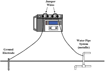
The final simplified method is again one of limited reliability, and should not be employed generally; that is the “Dead Earth” Method. This technique is quite popular because of its simplicity. Only two leads are used, one hooked to the test ground and one to a reference ground (Fig. 5). This is essentially the same as using a multimeter, and was described earlier in this article. The use of a ground tester can eliminate the interference problem for reasons already presented, but the unreliability of the reference ground and the problem of insufficient separation still exist. Accordingly, IEEE 81 advises, “…This method is subject to large errors for low-valued driven grounds but is very useful and adequate where a ‘go, no-go’ type of test is all that is required.”
“Clamp-on” Method
Ground testers of the clamp-on style have only been available for about ten years. These units combine form and function so that the tester and method are one and the same. “Clampon” jaws contain both voltage and current windings. They can be clamped over a ground rod or grounding conductor and will inject a test current into the system. The current travels through the soil, seeks its own return through a parallel ground, and loops back through the system neutral. The voltage transformer senses the voltage drop around the loop and the tester calculates resistance. It’s disarmingly simple to use, and thereby lies both its strength and danger.
The astute reader will already have noticed the parallel with the multimeter technique. By injecting a current signal, the clamp-on takes advantage of the electrical system to provide a return, thereby removing dependency on an arbitrary “dead earth” reference. Some peril still remains in the return path and, lacking control of test probes, the operator is at its mercy. An oscillator produces a distinctive frequency and filters help suppress interference. The resultant measurement is a series resistance, which should be comprised almost entirely of the contribution from the soil. The method also simultaneously checks the bonding of grounding conductors, so that an open or corroded bond would show up in a high measurement.
Early models had shortcomings regarding accuracy, especially at the lower readings associated with commercial grounds, and were even banned by some authorities. However, technological improvements have corrected these failings to the extent that modern units are highly accurate and reliable. Some caveats remain, however. A traditional model can be utilized anywhere, but not a clamp-on. They obviously cannot be used for commissioning of new grounds that have not been connected. The operator must have a thorough understanding of the electrical plan, so that there are no feedback loops that short-circuit the soil altogether. Multiply connected grounds can circulate test current within their own structure, providing no more than a continuity test. Yet operators may be all too willing to accept these as “proof ” of a good ground. Finally, the method does not afford the protection of a reference to an independent standards organization.
Slope Method
Other methods have been devised to cope with the other major problem of ground testing, limited space. To develop a full Fall of Potential graph, leads may have to be run out hundreds of feet, and tests have even been performed for miles! Such practice may be unacceptable or impossible for a variety of reasons: property lines, obstructions like highways, waterways, and railroads, congested urban sites, or large ground grids, especially in areas of poor soil. The most prevalent method of dealing with this problem is the Slope Method. Again, a mathematical simplification derived from calculus is employed, this time to find the point on a graph such as shown in Fig. 4 where the resistance of the test ground stops and that of the current probe takes over. This obviously cannot be read from the graph, so a mathematical exercise is employed to find it. Readings are taken at 20, 40 and 60% of the distance, and a calculation made to determine a slope coefficient. Tables found commonly in the literature are referenced for a corresponding ratio of potential probe distance to current probe distance (dPT/dC), and when multiplied by the known distance to the current probe gives the position at which the potential probe should be placed to derive the correct reading. If the current probe is so close that it is within the field of the test ground, the mathematics will prove unintelligible and indicate to the operator that a better test position must be found.
Star-Delta
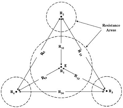
If this latter condition prevails, and room is so limited that an acceptable spacing cannot be derived even with the Slope Method, it may be necessary to resort to Star-Delta. Named for the configuration of the test probes and lines of measurement (a graphic of it resembles the familiar symbols for “delta” and “star” windings), this method saves space by employing a tight configuration of three probes around the test ground (Fig. 6). Separation of potential and current circuits is abandoned, and a series of two-point measurements made between all pairs of probes and probes to test ground. This results in six measurements that are then put through a mathematical “crunch” of four series equations to calculate the resistance of the test ground. As with all mathematical methods, a faulty or unreliable setup produces unintelligible calculations (e.g., “negative” resistances), and so the operator knows that the procedure needs to be spruced up.
“Intersecting Curves”
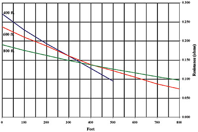
A very difficult and tedious method, but ideal for those who welcome a challenge, is that of “Intersecting Curves”. Very large grids are not only likely to have commensurately large electrical fields that require impractically long leads in order to test, but also compound the problem by having indeterminate electrical centers (which do not necessarily coincide with the geometric center). Obviously, for measurement purposes, a single rod can be treated as a point, and a small grid or array doesn’t offer enough of an error to be significant. But with large grids, the uncertainty as to the actual distance of separation from the current probe can become a complication. In the Intersecting Curves method, a number of resistance-versus-distance graphs are first constructed at different lead lengths. The unknown distance between the convenient point of attachment and the electrical center is assigned a number of arbitrary values, and using the 62 % rule, the corresponding positions are calculated for the potential probe. The corresponding resistances for each of these points can then be read from one of the graphs. These resistances are then plotted against their arbitrary unknown distances on another graph. This process is repeated for each of the measurement graphs, and additional lines constructed on the second graph accordingly. If the test setup were ideal, these dreivative graphs would all intersect at a single point. In the real world, they are more likely to form a tight triangle, the center of which corresponds to the actual resistance of the test ground (Fig. 7). The correct unknown distance can also be read, and if this is plugged back into the equation for distance to the potential probe, a measurement can be taken at that actual point and should agree with the one read from the graph.
Soil Resistivity
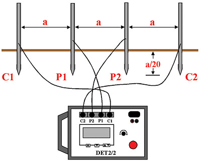
If measured resistances are unacceptable, the test ground must be improved. This is accomplished by driving deeper rods, adding more rods, or applying various chemical treatments or backfills. This can be done by trial and error, but a more efficient method is to first take electrical measurements of the properties of the soil itself, and then apply this data to the construction, location, or improvement of grounding electrodes. A number of standard procedures exist, but by far the method of choice is the “Wenner” Method. Four probes are arranged at equal distances, and driven 1/20th of their horizontal separation (Fig. 8). Such an arrangement will measure average soil resistivity to a depth equivalent to the spacing. The tester is then energized and a reading taken. This is plugged into the “Wenner Formula”:
r = 2paR
where:
r = average soil resistivity (typically in units of ohm-cm)
a = probe spacing (typically in cm)
R = resistance reading
The data is called the resistivity of the soil, as opposed to the resistance of a buried electrode. It indicates how the soil will respond to the flow of electric current, and is invaluable to any effort to establish maximum grounding protection.
Conclusion
While the NEC is indispensable to electrical safety, its recommendations are not all inclusive. For commercial applications, it is wise to establish ground protection to its maximum level, not simply conform to a minimum. This cannot be accomplished without testing, and it cannot be accomplished properly without proper instrumentation and procedures.
ABOUT THE AUTHOR
Jeff Jowett is a Senior Application Engineer with Megger. He has been with Megger for over 30 years specializing in electrical testing applications in the areas of insulation resistance testing, ground resistance testing and low resistance ohmmeter testing. He is a regular speaker at industry events and dozens of articles authored by him have been published by various magazines worldwide.
Simplified Fall of Potential applies a mathematical proof to the fundamental concept already described. Rather than taking the time and work of plotting at regular intervals across the full span from test electrode to current probe, the initial measurement is made at the midway point, then two more at 10% of the distance in either direction. This is a lot less time consuming, and its success is determined by whether or not the three readings were taken on the plateau of the underlying Fall of Potential graph, or on the rising curve. To make this determination, a simple mathematical procedure is applied, derived from calculus and based on rate of change of slope. The calculation yields a percent accuracy of the average of the three readings. If the readings are not sufficiently grouped within a narrow tolerance, the average falls outside an acceptable accuracy, and they were likely made on the rising curve. The procedure must be repeated at greater distance.
The worldly-wise will ask, “Why don’t we just look at a few successive readings and see if they agree?” This represents a non-descriptive procedure that is widely performed, and might be called the “eyeball” method. If the technician is sufficiently experienced, it may be reasonably reliable. However, it lacks objectivity, and won’t likely stand up to third-party scrutiny. The readings may fall on the rising curve or may reflect only random variations, and the operator’s judgment may be tainted by optimism. Invoking the mathematical proof of the Simplified Fall removes this potential source of error.
“62% Rule”
Simpler still is the widely known “62% Rule”. This is a single measurement, taken at 62% (actually 61.8) of the distance to the current probe. Remember that on a classic Fall of Potential graph, the current probe superimposes its own sphere of resistance. Therefore, at some point, the graph must coincide with the value of the true theoretical resistance, if it were possible to measure the entire planet from the point of the test ground. That coincidence has been mathematically determined to occur at the 61.8% distance. Why isn’t all ground testing done to that point, then? The reason is because the determination is based on an ideal model. In actual practice, the current probe may not be far enough away, there may be a pipe or power cable directly under the potential probe, or the spot may have been filled with some non-representative material. For these reasons, the 62% Rule should not be relied upon at unknown sites, but is a good backup test at areas that have already been rigorously proofed.
“Dead Earth”
The final simplified method is again one of limited reliability, and should not be employed generally; that is the “Dead Earth” Method. This technique is quite popular because of its simplicity. Only two leads are used, one hooked to the test ground and one to a reference ground (Fig. 5). This is essentially the same as using a multimeter, and was described earlier in this article. The use of a ground tester can eliminate the interference problem for reasons already presented, but the unreliability of the reference ground and the problem of insufficient separation still exist. Accordingly, IEEE 81 advises, “…This method is subject to large errors for low-valued driven grounds but is very useful and adequate where a ‘go, no-go’ type of test is all that is required.”

Figure #5: “Dead Earth” Test
“Clamp-on” Method
Ground testers of the clamp-on style have only been available for about ten years. These units combine form and function so that the tester and method are one and the same. “Clampon” jaws contain both voltage and current windings. They can be clamped over a ground rod or grounding conductor and will inject a test current into the system. The current travels through the soil, seeks its own return through a parallel ground, and loops back through the system neutral. The voltage transformer senses the voltage drop around the loop and the tester calculates resistance. It’s disarmingly simple to use, and thereby lies both its strength and danger.
The astute reader will already have noticed the parallel with the multimeter technique. By injecting a current signal, the clamp-on takes advantage of the electrical system to provide a return, thereby removing dependency on an arbitrary “dead earth” reference. Some peril still remains in the return path and, lacking control of test probes, the operator is at its mercy. An oscillator produces a distinctive frequency and filters help suppress interference. The resultant measurement is a series resistance, which should be comprised almost entirely of the contribution from the soil. The method also simultaneously checks the bonding of grounding conductors, so that an open or corroded bond would show up in a high measurement.
Early models had shortcomings regarding accuracy, especially at the lower readings associated with commercial grounds, and were even banned by some authorities. However, technological improvements have corrected these failings to the extent that modern units are highly accurate and reliable. Some caveats remain, however. A traditional model can be utilized anywhere, but not a clamp-on. They obviously cannot be used for commissioning of new grounds that have not been connected. The operator must have a thorough understanding of the electrical plan, so that there are no feedback loops that short-circuit the soil altogether. Multiply connected grounds can circulate test current within their own structure, providing no more than a continuity test. Yet operators may be all too willing to accept these as “proof ” of a good ground. Finally, the method does not afford the protection of a reference to an independent standards organization.
Slope Method
Other methods have been devised to cope with the other major problem of ground testing, limited space. To develop a full Fall of Potential graph, leads may have to be run out hundreds of feet, and tests have even been performed for miles! Such practice may be unacceptable or impossible for a variety of reasons: property lines, obstructions like highways, waterways, and railroads, congested urban sites, or large ground grids, especially in areas of poor soil. The most prevalent method of dealing with this problem is the Slope Method. Again, a mathematical simplification derived from calculus is employed, this time to find the point on a graph such as shown in Fig. 4 where the resistance of the test ground stops and that of the current probe takes over. This obviously cannot be read from the graph, so a mathematical exercise is employed to find it. Readings are taken at 20, 40 and 60% of the distance, and a calculation made to determine a slope coefficient. Tables found commonly in the literature are referenced for a corresponding ratio of potential probe distance to current probe distance (dPT/dC), and when multiplied by the known distance to the current probe gives the position at which the potential probe should be placed to derive the correct reading. If the current probe is so close that it is within the field of the test ground, the mathematics will prove unintelligible and indicate to the operator that a better test position must be found.
Star-Delta
If this latter condition prevails, and room is so limited that an acceptable spacing cannot be derived even with the Slope Method, it may be necessary to resort to Star-Delta. Named for the configuration of the test probes and lines of measurement (a graphic of it resembles the familiar symbols for “delta” and “star” windings), this method saves space by employing a tight configuration of three probes around the test ground (Fig. 6). Separation of potential and current circuits is abandoned, and a series of two-point measurements made between all pairs of probes and probes to test ground. This results in six measurements that are then put through a mathematical “crunch” of four series equations to calculate the resistance of the test ground. As with all mathematical methods, a faulty or unreliable setup produces unintelligible calculations (e.g., “negative” resistances), and so the operator knows that the procedure needs to be spruced up.

Figure #6: Star-Delta Method
“Intersecting Curves”
A very difficult and tedious method, but ideal for those who welcome a challenge, is that of “Intersecting Curves”. Very large grids are not only likely to have commensurately large electrical fields that require impractically long leads in order to test, but also compound the problem by having indeterminate electrical centers (which do not necessarily coincide with the geometric center). Obviously, for measurement purposes, a single rod can be treated as a point, and a small grid or array doesn’t offer enough of an error to be significant. But with large grids, the uncertainty as to the actual distance of separation from the current probe can become a complication. In the Intersecting Curves method, a number of resistance-versus-distance graphs are first constructed at different lead lengths. The unknown distance between the convenient point of attachment and the electrical center is assigned a number of arbitrary values, and using the 62 % rule, the corresponding positions are calculated for the potential probe. The corresponding resistances for each of these points can then be read from one of the graphs. These resistances are then plotted against their arbitrary unknown distances on another graph. This process is repeated for each of the measurement graphs, and additional lines constructed on the second graph accordingly. If the test setup were ideal, these dreivative graphs would all intersect at a single point. In the real world, they are more likely to form a tight triangle, the center of which corresponds to the actual resistance of the test ground (Fig. 7). The correct unknown distance can also be read, and if this is plugged back into the equation for distance to the potential probe, a measurement can be taken at that actual point and should agree with the one read from the graph.

Figure #7: Intersecting Curves Graph
Soil Resistivity
If measured resistances are unacceptable, the test ground must be improved. This is accomplished by driving deeper rods, adding more rods, or applying various chemical treatments or backfills. This can be done by trial and error, but a more efficient method is to first take electrical measurements of the properties of the soil itself, and then apply this data to the construction, location, or improvement of grounding electrodes. A number of standard procedures exist, but by far the method of choice is the “Wenner” Method. Four probes are arranged at equal distances, and driven 1/20th of their horizontal separation (Fig. 8). Such an arrangement will measure average soil resistivity to a depth equivalent to the spacing. The tester is then energized and a reading taken. This is plugged into the “Wenner Formula”:
r = 2paR
where:
r = average soil resistivity (typically in units of ohm-cm)
a = probe spacing (typically in cm)
R = resistance reading
The data is called the resistivity of the soil, as opposed to the resistance of a buried electrode. It indicates how the soil will respond to the flow of electric current, and is invaluable to any effort to establish maximum grounding protection.

Figure#8: Wenner Method
Conclusion
While the NEC is indispensable to electrical safety, its recommendations are not all inclusive. For commercial applications, it is wise to establish ground protection to its maximum level, not simply conform to a minimum. This cannot be accomplished without testing, and it cannot be accomplished properly without proper instrumentation and procedures.
ABOUT THE AUTHOR
Jeff Jowett is a Senior Application Engineer with Megger. He has been with Megger for over 30 years specializing in electrical testing applications in the areas of insulation resistance testing, ground resistance testing and low resistance ohmmeter testing. He is a regular speaker at industry events and dozens of articles authored by him have been published by various magazines worldwide.


