
"Meeting Code"
In its common form, grounding is typically thought of as no more than a rod driven into the earth in order to provide a safe diversion of lightning strokes. In a sense, the National Electric Code‚ (NEC‚) indirectly provides a basis for this conception. The Code requires that a single rod or other approved electrode be installed in the soil and tested. If it tests at 25 W or less, the installation “meets Code”. If not, a second rod or other electrode is installed at least 6 feet away. It need not be retested. The additional electrode can routinely be expected to reduce the measurement by about 40%, but that still says almost nothing about what the final value might be.
However, meeting code is not all there is to ground protection. The Code is a working directive promoting electrical safety. It tacitly acknowledges that soil conditions are so variable that to insist on a universal absolute would be impractical and unfair. A homeowner who has the misfortune to live in an area of high soil resistivity cannot reasonably be expected to drive a ground rod halfway to China. If one is inadequate, the addition of a second will afford substantial improvement, and in the final analysis, “something is better than nothing.”
Likewise, in “meeting Code”, the implication is that the facility is safe, not necessarily functional. The Code is concerned with safety, not performance. The building may be protected from lightning and electrical faults, but still have “noise” on datacom lines. The familiar 25 W standard is actually very forgiving, selected for practicality and basic protection, not optimal design. In theory, one would want to ground an electrical system at zero resistance. But this, of course, is not possible in the real world. A realistic alternative goal is to get as close as possible, substantially cutting down the enormous gap between “making Code” and theoretical perfection.
On the “downstream” side of 25 W, there can be a nearly inverse relationship between resistance and performance. Aside from the NEC, no universal ground resistance standard exists. However, industry practices and insurance recommendations have established some familiar guidelines: 5 W for a typical commercial ground, 3 W for a chemical plant, 2 W (or even less!) for computer rooms and process-control operations, 1 W for large utility substations and generating plants. And if anything, these practices are becoming more demanding. The increasing reliance on computer operations, process control, and datacom/telecom functions has made the presence of “noise” intolerable. With data signals as narrow as 3 V, or even 1.5, the differences between “Xs” and “Os” can be scrambled by noise that means nothing to the operation of standard 120/240 equipment. Voltage regulation is important as never before, and ground is critical in the mitigation of internally generated noise as well as external fault and disturbances.
Therefore, the popular image of a single rod for lightning protection is only the beginning. This paper will deal with ground testing as it fits in with the implementation of maximum grounding efficiency. To attain a high level of protection, one must first know how to measure. The practice of ground testing is much abused, primarily through failure to recognize its unique properties. Proper measurement breaks down into two elements: equipment and procedure.
The Right Equipment
Good ground measurement begins with proper equipment. Ground testing presents challenges unlike any other in the arena of electrical testing. The first line of error is one of faulty logic: to make a resistance measurement requires an ohmmeter. Wrong! To perform a ground test, it requires a ground tester; that is to say, an instrument specifically designed to meet the unique factors involved in testing unlimited earth. A common mistake is to use a generic multimeter, with one lead connected to the test ground and the other to an arbitrary reference ground. This procedure will provide a measurement, but the critical question is, what is it actually measuring? This technique suffers from at least three potential sources of error: interference, extraneous resistances, and the arbitrary position of the reference.
The fact is easily overlooked, but the earth carries a lot of “noise” from transients trying to find their way back to transformer secondaries. Multimeters are dc testers, and their readings will be influenced by whatever voltages may be present in the soil. The operator may be made aware by destabilization of the display, but there is no specific indicator to provide warning. Secondly, the reading…influenced or not…is a series resistance that includes the soil and everything else in the loop. It would be nice if this were zero, but that’s not likely. The reference ground is assumed to make a negligible contribution, but that is only an assumption, largely untestable. The most commonly employed reference is the water-pipe system, but if this has been repaired with plastic pipe or couplers, its usefulness is negated. Finally, even if there is no interference or additional resistance from the reference, the reading still may not be reliable. Under these latter circumstances, a generic multimeter may provide a good reading of soil resistance between the two points. This may be an accurate measurement of ground resistance…and it may not. It can only be accepted on faith.
Most electrical testing is performed on discrete circuits of human design. The elements are known and their properties can be routinely addressed. Not with ground testing. Making an electrical connection to a grounding electrode thereby includes the entire planet Earth. In theory, a “true” resistance measurement would have to be made at “infinite distance”; i.e., including the whole planet. Of course, this cannot be done, and doesn’t have to be. The area immediately surrounding the electrode provides 99.999...n% of the resistance, and the rest of the planet is only of theoretical interest. The “test item”, then, is the electrode and its immediate surrounding soil (Fig. 1). This cannot be manipulated like a piece of apparatus. Rather, the tester has to be accommodated to the possibilities.
Dedicated Ground Testers
Dedicated ground testers operate with an alternating square wave of a distinct frequency apart from what is likely to be produced by utility harmonics (Fig. 2).
They recognize their own signal and, unlike a multimeter, disregard “noise”. If soil transients are extreme, to the extent that the tester’s filtering capabilities are overridden, warning indicators let the operator know that a problem exists so that faulty readings are not blindly recorded. Furthermore, the ac signal facilitates the use of the virtually limitless lead lengths that are required when testing large grids in poor soil conditions. Finally, a ground tester is not a two-terminal device but is designed according to the four-wire Kelvin bridge principle. Having two separate current and two separate voltage terminals enables the operator to have complete control of the test setup. The reliability of the test is not at the mercy of fixed-position reference grounds. The operator drives probes exactly where desired, so that it is known precisely what is being measured. Furthermore, the separate voltage probe enables surveying of the entire test site in order to recognize local anomalies, determine representative conditions for the area, and proof the readings, as will be described under the discussion of methods. The Kelvin configuration further eliminates all extraneous resistances, as from leads and contacts, so that the tester provides a precise measurement, not an approximation.
Correct Procedure
The right instrumentation must be accompanied by the right procedure. In no area of electrical testing is procedure more important than in ground testing. It is not simply a matter of hooking up and pressing a button. The test item is uncontrolled and uncontrollable…a substantial and unknown volume of earth surrounding the buried electrode in three dimensions. Electrical circuits are typically made of relatively pure materials with narrow tolerances, but not in this case!
Because soil is almost infinitely variable, both in terms of composition and the temporal effects of weather, there is no way of knowing, prior to testing, what volume comprises the effective resistance at a particular site. The literature is full of tables that provide guidelines, but these are only suggestions meant to give a fair chance of performing an acceptable test on the first trial. To simply place probes and take a reading will provide an accurate measurement of soil resistance between the two points, the test electrode and the potential probe. This may or may not be the effective resistance that a fault current will encounter. To make that determination, the site must be rigorously proofed. Operation of the tester alone does not provide this. It must be augmented by a proper procedure.
Fall of Potential
The basis for all accepted methods is defined by IEEE (Institute of Electrical and Electronics Engineers) Standard 81, and is called “Fall of Potential”.
Making use of the separate voltage probe, the procedure consists of plotting the resistance from the test electrode to a regular succession of points in the direction of the current probe. This procedure develops a profile of the soil, indicates discontinuities and non-uniformity, and provides much more information than would a single measurement. Ideally, a Fall of Potential test should produce a graph that looks like Fig. 3.
This shows that if the measurement were taken infinitely close to the test ground, the resistance would be infinitely small, as would be expected. This is evident from the simple fact that, at for instance one foot, there is very little soil to offer resistance. Such a measurement would be of no practical value, however (except possibly to fool an unapprised client or inspector!). As the probe is moved farther out and additional readings taken, the increased travel through soil adds resistance, just as a two-foot wire offers more resistance than a one-foot section of the same wire. But a funny thing happens on the way to the current probe! Readings level off and remain essentially flat, until the approach to the current probe constricts the path and superimposes additional resistance. Hence, the graph rises toward the end.
The distinctive shape of the graph is generated by soil volume. Soil is a “good conductor” because of its enormity and ubiquity. Fault current through a grounding electrode isn’t restricted to a straight path from point a to b, as in a designed circuit. Rather, it radiates in all directions, 360° from the electrode. The current path spreads out, rather than traveling in a straight line. Soil in the relatively narrow confines around the electrode offers some resistance, but at greater distance, the area becomes so vast that there is no increase in resistance large enough to be measured. Soil volume is the reason that the graph eventually reaches a stable plateau, and if that were not so, grounding itself would not be possible.
Constructing a Fall of Potential graph, then, shows the relationship between space and resistance. The value where the readings stop increasing is the measure of the effective resistance of the test ground. This could be at virtually any value up into hundreds of ohms. But if it is above 25, it’s not meeting Code, and not functioning as an effective ground. The distance at which this occurs marks the volume of soil that is the determining factor. This could be only a few feet in prime soil, but could be hundreds of feet or more in areas of high resistivity. Because this relationship...volume versus resistance…is so flexible, both the tester and the procedure must be adapted to meet the demands.
Performing a full Fall of Potential test is rigorous enough to stand up to any scrutiny. If the test electrode has a large "footprint", or electrical field in the soil…either from physical size or poor soil conductivity…the current probe may overlap and obscure the point of maximum resistance for the test ground. In such a situation, as the potential probe is moved, it would run directly into the superimposed resistance associated with the current probe. This would produce a graph that looks like that in Fig. 4. One of the strengths of this method is that it affords a built-in proof. If a graph like that in Fig. 4 is produced, the current probe is moved farther out and the procedure repeated. No such proof is available with any other instrument than a dedicated ground tester.
Test Methods
A graph as ideal as that in Fig. 3 is not likely to be produced by a real test. Field experience becomes a valuable ally. Buried objects can cause dips and bumps. Soil variations, especially at graded construction sites, can create a wavy plateau. But an unreadable graph is a clear indication of an unacceptable test. The operator has to repeat, perhaps in another direction, but will not be led astray by a “bad” reading, unaware. The limitations of this method are that it is a lot of time and work, and also may require more lead distance than is available, especially at an urban site. Accordingly, many variations and additional methods have been devised, some for general application and some for specific situations. Additional methods are frequently based on simplifications of the Fall of Potential concept, and sometimes on other mathematical abstractions. Test methods serve two purposes: to provide a proof that the reading actually represents the effective resistance and is not some random measurement, and to permit some simplification either in terms of speed or the means of dealing with some specific challenge.
Those aimed at shortening test time are the Simplified Fall of Potential, 62% Rule, “Dead Earth” Method, and one that for want of any real name might be called the “eyeball” method. Those designed to meet challenges, specifically of limited space as opposed to limited time, are the Slope Method, Star-Delta Method, and “Intersecting Curves”. Finally, for measuring the electrical conductivity of soil itself, there is the Wenner Method.
In Part2 we will examine each of these test methods in detail.
In its common form, grounding is typically thought of as no more than a rod driven into the earth in order to provide a safe diversion of lightning strokes. In a sense, the National Electric Code‚ (NEC‚) indirectly provides a basis for this conception. The Code requires that a single rod or other approved electrode be installed in the soil and tested. If it tests at 25 W or less, the installation “meets Code”. If not, a second rod or other electrode is installed at least 6 feet away. It need not be retested. The additional electrode can routinely be expected to reduce the measurement by about 40%, but that still says almost nothing about what the final value might be.
However, meeting code is not all there is to ground protection. The Code is a working directive promoting electrical safety. It tacitly acknowledges that soil conditions are so variable that to insist on a universal absolute would be impractical and unfair. A homeowner who has the misfortune to live in an area of high soil resistivity cannot reasonably be expected to drive a ground rod halfway to China. If one is inadequate, the addition of a second will afford substantial improvement, and in the final analysis, “something is better than nothing.”
Likewise, in “meeting Code”, the implication is that the facility is safe, not necessarily functional. The Code is concerned with safety, not performance. The building may be protected from lightning and electrical faults, but still have “noise” on datacom lines. The familiar 25 W standard is actually very forgiving, selected for practicality and basic protection, not optimal design. In theory, one would want to ground an electrical system at zero resistance. But this, of course, is not possible in the real world. A realistic alternative goal is to get as close as possible, substantially cutting down the enormous gap between “making Code” and theoretical perfection.
On the “downstream” side of 25 W, there can be a nearly inverse relationship between resistance and performance. Aside from the NEC, no universal ground resistance standard exists. However, industry practices and insurance recommendations have established some familiar guidelines: 5 W for a typical commercial ground, 3 W for a chemical plant, 2 W (or even less!) for computer rooms and process-control operations, 1 W for large utility substations and generating plants. And if anything, these practices are becoming more demanding. The increasing reliance on computer operations, process control, and datacom/telecom functions has made the presence of “noise” intolerable. With data signals as narrow as 3 V, or even 1.5, the differences between “Xs” and “Os” can be scrambled by noise that means nothing to the operation of standard 120/240 equipment. Voltage regulation is important as never before, and ground is critical in the mitigation of internally generated noise as well as external fault and disturbances.
Therefore, the popular image of a single rod for lightning protection is only the beginning. This paper will deal with ground testing as it fits in with the implementation of maximum grounding efficiency. To attain a high level of protection, one must first know how to measure. The practice of ground testing is much abused, primarily through failure to recognize its unique properties. Proper measurement breaks down into two elements: equipment and procedure.
The Right Equipment
Good ground measurement begins with proper equipment. Ground testing presents challenges unlike any other in the arena of electrical testing. The first line of error is one of faulty logic: to make a resistance measurement requires an ohmmeter. Wrong! To perform a ground test, it requires a ground tester; that is to say, an instrument specifically designed to meet the unique factors involved in testing unlimited earth. A common mistake is to use a generic multimeter, with one lead connected to the test ground and the other to an arbitrary reference ground. This procedure will provide a measurement, but the critical question is, what is it actually measuring? This technique suffers from at least three potential sources of error: interference, extraneous resistances, and the arbitrary position of the reference.
The fact is easily overlooked, but the earth carries a lot of “noise” from transients trying to find their way back to transformer secondaries. Multimeters are dc testers, and their readings will be influenced by whatever voltages may be present in the soil. The operator may be made aware by destabilization of the display, but there is no specific indicator to provide warning. Secondly, the reading…influenced or not…is a series resistance that includes the soil and everything else in the loop. It would be nice if this were zero, but that’s not likely. The reference ground is assumed to make a negligible contribution, but that is only an assumption, largely untestable. The most commonly employed reference is the water-pipe system, but if this has been repaired with plastic pipe or couplers, its usefulness is negated. Finally, even if there is no interference or additional resistance from the reference, the reading still may not be reliable. Under these latter circumstances, a generic multimeter may provide a good reading of soil resistance between the two points. This may be an accurate measurement of ground resistance…and it may not. It can only be accepted on faith.
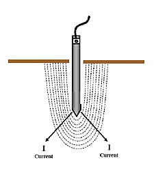
Figure #1: Grounding Electrode & Immediate Surrounding Soil
Most electrical testing is performed on discrete circuits of human design. The elements are known and their properties can be routinely addressed. Not with ground testing. Making an electrical connection to a grounding electrode thereby includes the entire planet Earth. In theory, a “true” resistance measurement would have to be made at “infinite distance”; i.e., including the whole planet. Of course, this cannot be done, and doesn’t have to be. The area immediately surrounding the electrode provides 99.999...n% of the resistance, and the rest of the planet is only of theoretical interest. The “test item”, then, is the electrode and its immediate surrounding soil (Fig. 1). This cannot be manipulated like a piece of apparatus. Rather, the tester has to be accommodated to the possibilities.
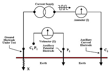
Figure #2: Four-Terminal Ground Tester
Dedicated Ground Testers
Dedicated ground testers operate with an alternating square wave of a distinct frequency apart from what is likely to be produced by utility harmonics (Fig. 2).
They recognize their own signal and, unlike a multimeter, disregard “noise”. If soil transients are extreme, to the extent that the tester’s filtering capabilities are overridden, warning indicators let the operator know that a problem exists so that faulty readings are not blindly recorded. Furthermore, the ac signal facilitates the use of the virtually limitless lead lengths that are required when testing large grids in poor soil conditions. Finally, a ground tester is not a two-terminal device but is designed according to the four-wire Kelvin bridge principle. Having two separate current and two separate voltage terminals enables the operator to have complete control of the test setup. The reliability of the test is not at the mercy of fixed-position reference grounds. The operator drives probes exactly where desired, so that it is known precisely what is being measured. Furthermore, the separate voltage probe enables surveying of the entire test site in order to recognize local anomalies, determine representative conditions for the area, and proof the readings, as will be described under the discussion of methods. The Kelvin configuration further eliminates all extraneous resistances, as from leads and contacts, so that the tester provides a precise measurement, not an approximation.
Correct Procedure
The right instrumentation must be accompanied by the right procedure. In no area of electrical testing is procedure more important than in ground testing. It is not simply a matter of hooking up and pressing a button. The test item is uncontrolled and uncontrollable…a substantial and unknown volume of earth surrounding the buried electrode in three dimensions. Electrical circuits are typically made of relatively pure materials with narrow tolerances, but not in this case!
Because soil is almost infinitely variable, both in terms of composition and the temporal effects of weather, there is no way of knowing, prior to testing, what volume comprises the effective resistance at a particular site. The literature is full of tables that provide guidelines, but these are only suggestions meant to give a fair chance of performing an acceptable test on the first trial. To simply place probes and take a reading will provide an accurate measurement of soil resistance between the two points, the test electrode and the potential probe. This may or may not be the effective resistance that a fault current will encounter. To make that determination, the site must be rigorously proofed. Operation of the tester alone does not provide this. It must be augmented by a proper procedure.
Fall of Potential
The basis for all accepted methods is defined by IEEE (Institute of Electrical and Electronics Engineers) Standard 81, and is called “Fall of Potential”.
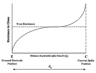
Figure #3: Fall of Potential Graph
Making use of the separate voltage probe, the procedure consists of plotting the resistance from the test electrode to a regular succession of points in the direction of the current probe. This procedure develops a profile of the soil, indicates discontinuities and non-uniformity, and provides much more information than would a single measurement. Ideally, a Fall of Potential test should produce a graph that looks like Fig. 3.
This shows that if the measurement were taken infinitely close to the test ground, the resistance would be infinitely small, as would be expected. This is evident from the simple fact that, at for instance one foot, there is very little soil to offer resistance. Such a measurement would be of no practical value, however (except possibly to fool an unapprised client or inspector!). As the probe is moved farther out and additional readings taken, the increased travel through soil adds resistance, just as a two-foot wire offers more resistance than a one-foot section of the same wire. But a funny thing happens on the way to the current probe! Readings level off and remain essentially flat, until the approach to the current probe constricts the path and superimposes additional resistance. Hence, the graph rises toward the end.
The distinctive shape of the graph is generated by soil volume. Soil is a “good conductor” because of its enormity and ubiquity. Fault current through a grounding electrode isn’t restricted to a straight path from point a to b, as in a designed circuit. Rather, it radiates in all directions, 360° from the electrode. The current path spreads out, rather than traveling in a straight line. Soil in the relatively narrow confines around the electrode offers some resistance, but at greater distance, the area becomes so vast that there is no increase in resistance large enough to be measured. Soil volume is the reason that the graph eventually reaches a stable plateau, and if that were not so, grounding itself would not be possible.
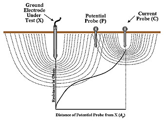
Figure #4: Non-Ideal Graph, Insufficient Probe Spacing
Constructing a Fall of Potential graph, then, shows the relationship between space and resistance. The value where the readings stop increasing is the measure of the effective resistance of the test ground. This could be at virtually any value up into hundreds of ohms. But if it is above 25, it’s not meeting Code, and not functioning as an effective ground. The distance at which this occurs marks the volume of soil that is the determining factor. This could be only a few feet in prime soil, but could be hundreds of feet or more in areas of high resistivity. Because this relationship...volume versus resistance…is so flexible, both the tester and the procedure must be adapted to meet the demands.
Performing a full Fall of Potential test is rigorous enough to stand up to any scrutiny. If the test electrode has a large "footprint", or electrical field in the soil…either from physical size or poor soil conductivity…the current probe may overlap and obscure the point of maximum resistance for the test ground. In such a situation, as the potential probe is moved, it would run directly into the superimposed resistance associated with the current probe. This would produce a graph that looks like that in Fig. 4. One of the strengths of this method is that it affords a built-in proof. If a graph like that in Fig. 4 is produced, the current probe is moved farther out and the procedure repeated. No such proof is available with any other instrument than a dedicated ground tester.
Test Methods
A graph as ideal as that in Fig. 3 is not likely to be produced by a real test. Field experience becomes a valuable ally. Buried objects can cause dips and bumps. Soil variations, especially at graded construction sites, can create a wavy plateau. But an unreadable graph is a clear indication of an unacceptable test. The operator has to repeat, perhaps in another direction, but will not be led astray by a “bad” reading, unaware. The limitations of this method are that it is a lot of time and work, and also may require more lead distance than is available, especially at an urban site. Accordingly, many variations and additional methods have been devised, some for general application and some for specific situations. Additional methods are frequently based on simplifications of the Fall of Potential concept, and sometimes on other mathematical abstractions. Test methods serve two purposes: to provide a proof that the reading actually represents the effective resistance and is not some random measurement, and to permit some simplification either in terms of speed or the means of dealing with some specific challenge.
Those aimed at shortening test time are the Simplified Fall of Potential, 62% Rule, “Dead Earth” Method, and one that for want of any real name might be called the “eyeball” method. Those designed to meet challenges, specifically of limited space as opposed to limited time, are the Slope Method, Star-Delta Method, and “Intersecting Curves”. Finally, for measuring the electrical conductivity of soil itself, there is the Wenner Method.
In Part2 we will examine each of these test methods in detail.