The substations in the electrical power system have undergone considerable developments through the use of modern primary apparatus, the use of microprocessors in the secondary equipment and the improved speed and capacity of communication to and within the substation. However at the same time the concept of building the stations has been very static and conservative using a considerable amount of discrete items and equipments such as control cables, control, metering and protection devices, RTU’s for SCADA communication etc.
Owners have conventionally segregated the responsibilities for control, protection, metering and communication both in terms of responsibilities and hardware. Design standards have been used in the power utilities for many years limiting the possibilities to fully adopt modern technologies and the full utilization of the emerging computer and Intelligent Electrical Device (IED) technologies. Standards have a great advantage in the management of stations for maintenance personnel but limit migration towards modern technologies. Stringent rules for maintenance often prevent effective and cost-saving use of the most modern equipment and the benefits of extensive self-supervision and self-testing facilities.

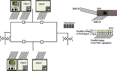
Figure 1. The structure of the typical North American substation using extensive discrete device wiring from each protection, control, instrumentation device, RTU and primary equipment.
System architecture for a modern homogeneous Substation Automation (SA) system.
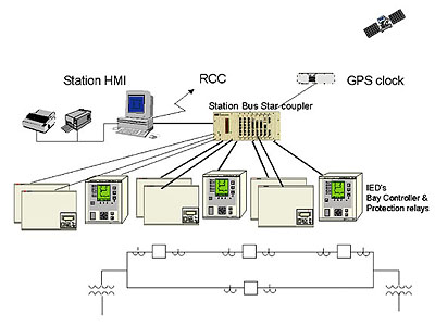
The Modern Substation Automation system (SA) is an open system. On station level the Ethernet or other high-speed station bus (e.g. LON) allows the integration of any equipment conforming to these standards. The basic configuration of a modern homogeneous SA system and its various components are illustrated in Figure 2. The system consists of a bay level, a station level, and an interconnecting communication medium, the Station-bus.

Figure 2. The structure of a typical substation automation system with substation control SCS and a remote gateway to Regional Control Centre (RCC)
The homogeneous SA system concept is based on achieving a very high reliability due to the decentralized solution and homogeneous IED and database structure. Different bays are independent and communicate to the Station HMI system and to the remote control at the Regional Control Centre (RCC) through the Station bus and a communication Gateway.
Security is achieved since equipment failure will never be allowed to cause loss of more than the defective device and the key components of the communication of the Station bus, are provided with duplicated auxiliary power supplies and independent interface cards for three nodes each (normally these nodes are modules from the same bay).
In this way a high reliability and availability is achieved without duplication of components. Reliability can be improved even further by the introduction of an emergency control of essential apparatus through the protection terminals using integral bay control and display capabilities.
A high flexibility for future expansion is achieved as the system is open for the addition of new and different types of existing modules depending on the need. It also allows for different levels of redundancy as required due to voltage level, station size and location.
Station Bus
The fast Station bus of the system (Fig. 2) utilizes a plastic or glass fiber-optic physical medium using industry standard secure connectors although plastic fibers can be used when distances and configuration requirement permit. Each bay unit (control or protection) has its own optical node within a star configuration. The star configuration has been selected to allow supervision of each individual node.
The new standard IEC 61850-9-1 is an open bus based on MMS over Ethernet and includes important functions such as peer-to-peer communication and transfer of time stamped messages. Speeds of 10 or 100 MBit/s can be realized today with 1GBit/s or greater capabilities anticipated in the future.
The existing LON bus has a transfer rate of 1.25 MBit/s. The maximum application-to-application transmission time for selected high-priority signals is less than 50 ms for units with LON interface. Hence, the time-critical signals for station interlocking can be sent across this bus. The security is further increased with a software reservation principle enabling real-time capabilities.
The star coupler in LON solution can be equipped with up to 25 fiber-optical ports with any combination of glass fibers, plastic fibers and electrical signals.
Time Synchronizing
Time synchronizing is an important part of a modern substation automation system. All occurring signals are time stamped on the lowest level when the signal occurs and the signals are sent with a “time-stamp” through the system. Synchronizing is provided using a GPS (Global positioning system) clock which sends signals to all connected IED’s through the communication bus and as a result only one time-signal connection to the system is required, realizing considerable installation cost savings. The software time synchronizing uses an advanced algorithm to adjust the clock so that accuracy is maintained independent of station bus loading.
Redundancy Concept
The decentralized solution can use single or redundant bay controllers and bay protection giving a high level of independence and reliability. The bay modules communicate via the star coupler in a star configuration preventing any potential problems in one bay from affecting other bays.
To enhance availability the Station bus and network switch is provided with redundant AC/DC auxiliary supplies, although DC is preferred. It also contains two or three channels per board, for redundancy on the card levels. Consequently an extremely high level of availability is achieved without duplication on bay level or duplicated communication channels.
The link to the Regional Control Center (RCC) is normally configured to be independent of the local operator’s workplace, although integrated alternatives can be supplied when required. The Station bus and the Protection and Control terminals supports a “multi-master” configuration and can therefore be connected to both the SA server and the RCC server. The SA & RCC servers are identical types of PC and provide a protocol converter for remote protocol support, typically normally IEC 870-5-101/4 or DNP3.0. The control and protection modules forming part of this SA system can handle three different masters in the system and redundancy can be achieved between Station and SCADA control and also within one of the two if required.
The total redundancy concept must be considered on case by case basis. In general today, most stations are unmanned and therefore a station computer with HMI and a separate Gateway computer is suitable. From the station computer a separate channel to the Regional Control Center (RCC) or National Control Centre (NCC) can be arranged either as a full gateway and/or as a LAN connection enabling control and monitoring with normal web-browsers and WAP telephones.
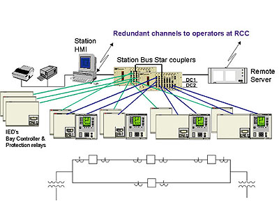
A Final Solution for Maximum Availability is Shown in Figure 3.
The bays include redundant protection and control modules. Each subsystem has an independent station bus with redundant supply and RCC control and station control is done through a fully independent system. To further increase availability from the RCC the Gateway communications software can also be included in the Station HMI computer. The system gives a maintenance free protection system as the operation of the protection terminals is supervised continuously by the RCC and station control system as an addition to the built-in self-supervision system in the numerical terminals.

Figure 3. The final concept for maximum availability and minimum maintenance demand.
Human Machine Interface
The station Human Machine interface is normally available from a local level at the controller IED and at a central station level from the station computer.
Selection of operators place always includes a priority where the local level has higher priority than the station central level and the station level has higher priority than the SCADA level.
The station control level is from the station computer monitor. The computer and the monitor should always be supplied from the station dc supply (battery) to avoid extra equipment e.g.UPS systems. This provides high availability for station control even with a fault on the applied network.
Apparatus Control
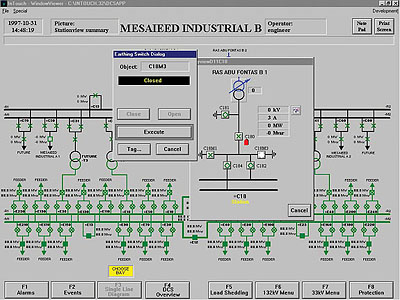
The operator can control the various objects in the substation displayed on the single-line diagram (see Figure 4) such as Circuit Breakers (CB), Disconnectors (DS), Grounding switches (ES), transformer tap changers (TC), and modify set-points, etc. via a command picture (opened in Figure 4), which appears upon selection of the particular object on the single-line diagram. The operation of apparatus is performed in two steps. First the mode of operation i. e. OPEN/ CLOSE is chosen and the selected apparatus will indicate it is selected for operation by changing color to white in the single-line diagram. In second step the operation is carried out by clicking on the EXECUTE key, i.e. the pre-selected command is then executed in the corresponding bay control unit.

Figure 4. The single line diagram with a bay control. Grounding switch is selected for operation.
When an apparatus is selected for operation the selected information will be given to other apparatus preventing operation of several apparatus at the same time. In the bay controller it is then checked for interlocking conditions permittion before execution of the command. Furthermore, the existence of blocking conditions e.g. low SF6 gas-pressure, are checked for the switching device (and in the case od circuit breakers also the Synchro-check verification). After successful termination of these checks the switching command is issued to the switching device using different control principles depending on the process requirements e. g. single or double command principle and single or double pole breaking.
Interlocking
The bay interlocking as well as the station-wide interlocking is performed using Boolean expressions implemented in the individual bay control units via an IEC1131 GUI configuration program. The station-wide interlocking expression requires switch position indications from other bays (e.g. busbar grounding switches, bus tie, bus coupler) are transferred to the corresponding bay control unit via the Station bus. A fail safe system requiring positive information from the bays to allow operation is used. The reliability will thus be very high and the speed requirement is kept down.
Scada Communication
The conventional SCADA communication through a hardware connected Remote Terminal Unit (RTU) is in this modern substation replaced with a communication gateway with full access to all data in the substation and with a remote communication protocol DNP3.0 or IEC 80-5-101/104 to the Regional Control Centre (RCC). Depending on the importance of the substation and the decided local control level different levels of redundancy can be utilized. Operators will have direct access to all values for control and operation but also information such as Disturbance recorder information (Oscillographs)
Summary of Advantages
The main objectives when designing a homogeneous substation automation SA system are to provide an increased reliability and performance over conventional systems whilst also offering economical improvement both in actual and installed costs. Many of the benefits result in cost savings and increased reliability.
Horizontal Integration.
The integration of control, protection and monitoring in one common system (horizontal integration) offers a remarkable advantage in different aspects:
- The common man-machine interface (HMI) of control, protection and monitoring on station reduces the training costs and simplifies planning, operation, maintenance and outage management.
- Adaptive Relaying, the synergy of control and protection, opens significant new possibilities such as enabling increased load without compromising protection integrity.
- Special Protection Systems such as Remedial Action Schemes for implementation of advanced load and generation control schemes.
Optical Fibers
The use of optical fibers instead of copper wires offers considerable savings in number of wires (fibres), installation time (duration and cost) and provides increased interference barrier capabilities.
Data Access and Gateways
The Homogeneous SA solutions also provides easy “plug & produce” access to the rich IED device databases and easy access of all data at the RCC instead of limited selected IED data.
Self Supervision and Reliabiliy
The modern IED’s used in the substation have extensive self-supervision features. The conventional solution uses separate equipments by function and in most cases on an independent phase-by-phase measurement basis, and connected by hard-wiring between relays and equipment. This is inherently fully redundant but fails to provide the additional data and functionality of modern IED’s. The high number of separate elements and discrete connections of the conventional solution gives potential failure points and to ensure that these equipment are fully available, extensive periodical maintenances is necessary. For the modern homogeneous substation as described, alarm and monitoring information is provided over the communications network and all IED’s are supervised giving a considerable increase of reliability.
Reduced Maintenance Demands and Increased Availability
The modern protection and control equipment terminals include extensive self supervision features and are connected to the SA system via serial communication in a star configuration and any IED failure will be immediately identified by the communication server resulting in better maintenance and outage management. Maintenance intervals of at least 5-6 years can now be used with maintained reliability as well as cost savings and increased total availability. The use of fewer componenets also results in less training and maintenance.
Cables and Erection
The considerable savings in cabling due to the extensive use of optical fibres for all signals between the IED’s and to the control and SCADA system, results in significant saving on cables, cable installation, testing, cable ducts, cables trays/ladders etc and result in shorter installation and erection times.
Commissioning
The commissioning includes signal verification for all signals. As the signals are software signals complete verification can be done on-line during the process of commissioning without extra signal verification to local control and SCADA system. The number wires to be verified is also drastically reduced as each signal is only brought into the control and protection system once.
Cost Benefits
The total installed and commissioned cost of relays is often many times the costs of the individual relay terminals or IED’s and can be 7-10 times the individual IED costs. Using a modern homogeneous Substation Automation solution can reduce this total installed cost to 4-7 times the comparable individual IED costs through a reduction of cabling, erection and other costs.
Modern Technology Benefits
Improved training and education of Personnel for maintenance and engineering through exposure and familiarity of modern technologies over traditional designs enabling the improved use and understanding of career building technologies and solutions.
About the Authors.
Max Degerfalt is Manager of Engineering with ABB Protection and Communications Group, Power Technologies Division (Utilities Automation) in Burlington, ON
Graham Herriman is Business Unit Manager of ABB Inc., Protection and Communications, PTUA in Burlington, ON


