
As an example, the final result of a cable failure may be that the insulation failed and the cable flashed over. The root cause may in fact be a building contractor removing thermally conducting back-fill around the ducts thereby causing local overheating. Determining the root cause of the failure can help prevent future failures.
Root cause analysis requires a systems approach. To help us in understanding this I will discuss cable components and the function of each of these components. I will also review cable systems, which include the cables, their accessories and operating environment. I will discuss electric fields within cables. I will then go over with some examples how evidence discovered in the analysis may lead to the root cause of the failure.
In this article, I will limit the discussion to medium voltage AC, 5 kV to 45 kV class cable systems. Keep in mind when we speak of the cable voltage class we mean the three-phase, lineto- line, nominal voltage of the system. I will cover only polymeric insulation, either polyethylene or Ethylene Propylene Rubber, because these are the most common insulations still in place.
Cable Components
Figure 1 shows a modern polyethylene cable designed to be used in a 25 kV system. The basic components from the inside out are:
- Conductor
- Conductor shield
- Insulation
- Insulation shield
- Metallic Shield
- Jacket or sheath (optional)
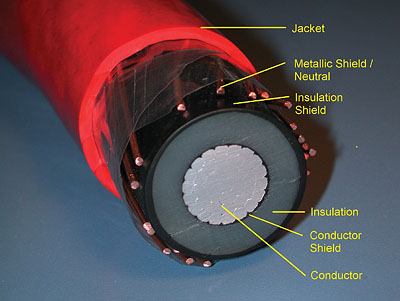
Figure 1. Primary distribution cable showing the cable components
The conductor is the current carrier of the cable and the most necessary part of any cable. Conductors are usually either copper or aluminum, and some may have plating. They can be solid in small sizes or stranded in larger sizes for better flexibility. The size of the conductor is determined using ampacity tables or computer based studies, and depends on current carrying requirements and cable surroundings. Fortunately very little can go wrong with a properly designed conductor, except for corrosion in some unusual cases.
The conductor shield is required particularly over stranded conductors in medium and high voltage cables. The conductor shield provides for a smooth, radial electric field within the insulation. In cables with polymeric insulation, the conductor shield is usually the same polymeric material as the insulation, but impregnated with carbon particles to make the material a semiconductor. The resistivity of the semicon is required by standards to be below 100 Ohm-meters, but modern semicons have lower resistivity, generally below 10 Ohmmeters. Semicon resistivity often increases with temperature, especially in older cables. Keep in mind that pure copper has a resistivity of about 18 x 10-9 Ohm-meters, and therefore is much more conductive than any semicon.
The insulation is arguably the second most important part of any cable, next to the conductor. Most cable insulation encountered today is polymeric, either polyethylene (PE) or ethylene propylene rubber (EPR). The majority of modern PE is cross-linked (XLPE). Almost all polymeric insulation compounds have proprietary additives to improve their expected life. An example is the “tree retardant” compound used in XLPE to slow the growth of water trees (TR-XLPE).
The insulation shield, like the conductor shield, is required in medium and high voltage cables. The properly functioning insulation shield provides for a smooth, radial electric field within the insulation. Materials used in the insulation shield are similar to those in the conductor shield. One important aspect of the insulation shield is its “strip-ability”. The insulation shield must be easily strippable in order to be terminated and spliced. However the semicon must remained firmly bonded to the insulation during operation to prevent small air pockets in which damaging partial discharges may occur.
The metallic shield is applied over the insulation shield and serves several purposes including:
- Providing a path for the flow of charging current
- Providing a path for the flow of fault current
- Reducing the touch potential in the event of a dig-in into the cable.
If the metallic shield is of sufficient size and conductivity, it can provide a path for the return current and thereby acts as a system neutral. The metallic shield/neutral is usually made of copper, but in some cases aluminum is used. There are a number of designs of metallic shields including round wire, flat strap, taped, and Longitudinally Corrugated (LC). An LC shield, shown in Figure 2, can also act as a hermetic seal, and prevent water from entering the insulation.
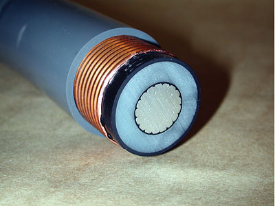
Figure 2. Longitudinally Corrugated (LC) metallic shield/neutral
Sometimes a number of single-phase cables are put together in a multi-phase cable. Figure 3 shows a cable in which three single-phase, shielded, EPR cables are contained in a threephase cable. The metallic shields on each phase are thin copper wires called drain wires. There are also three unshielded secondary cables used as neutral wires in the system.
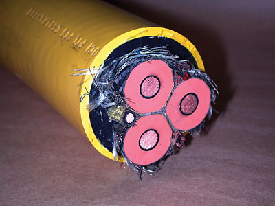
Figure 3. Three-phase EPR insulated cable.
The outer layer of any three-phase or singlephase cable may be a metal sheath, a plastic jacket or both. The cables in Figures 1 to 3 have only plastic jackets. The purpose of the jacket or sheath is for mechanical protection. If the sheath is solid metal, it also protects the cable from water ingress. The plastic jacket mechanically protects the cable and slows the ingress of water. Keep in mind that no plastic material will hermetically seal a cable from water ingress.
Some cables have special components other than those already discussed. These may include:
- Strand blocking material to keep water from flowing through the conductor to the insulation
- Water absorbing materials under the jacket to absorb or at least slow moisture ingress
- Layers needed to aid in the cable manufacture.
Power Cable Systems
One of the fundamental aspects of the cable system is the method of installation. Cable systems can be installed in various ways including:
- In trays or troughs, either in or out doors
- Suspended from poles, bridges, or walls of vaults or tunnels
- Buried in ducts or conduits, or direct buried (See Figure 4.)
- Under water as a submarine cable
- In special situations as mine trailing cables, crane cable etc.
Always keep in mind the installation when looking for the cause of a failure.
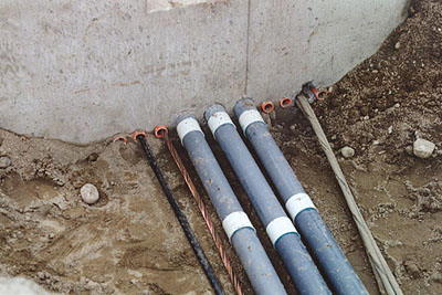
Figure 4. Installation showing direct buried cables and ducts.
Cable accessories are often the most prone to failure of any part of the cable system. Accessories include terminations and joints, also called splices. Terminations are required to connect the conductor of the cable to a bus or other cable conductor. Within the termination the cable’s metallic and semicon shields must also be properly terminated. Splices may be simply considered two terminations, connected back to back.
A type of medium voltage termination, called a load break Separable Insulated Connector (SIC), is designed to be disconnected from and reconnected to equipment under full load. SICs consist of an elbow, bushing insert and bushing well. SICs are some of the most complex medium voltage accessories, and can be prone to failures if not installed and operated correctly.
Another aspect of the cable system
is the operating environment. Some points of the operating environment, which must be considered, are:
- Cable current loading compared to cable ampacity
- Ambient temperature
- Type of backfill around direct buried cables or ducts
- Moisture or chemicals in contact with the cables and accessories
- Lightning impulses and other system induced over-voltages
- Switching operations.
Electric Fields in Cables
Before we get into failure analysis in cable systems, I would like to review electric fields within cables. It is important to examine some of the normal magnitudes and orientations of efields in cables, to understand how variations from the normal may lead to failures. Figure 5 shows a color contour plot of the electric field strength in a 25 kV cable (14.4 kV l-g) with an AWG 2/0 solid conductor, 6.6 mm of PE insulation and an insulation shield. In this case the field varies radially from 4 kV/mm at the conductor to 1.3 kV/mm at the insulation shield. Figure 6 shows a similar cable, without an insulation shield, near a grounded metal point. In this case the field near the point in the insulation is 7.4 kV/mm and near the point in air is 17.5 kV/mm.
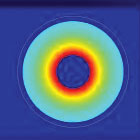
Figure 5. E-Field Color Contour Plot - 2/0 Conductor, 6.6 mm PE and 14.4 kV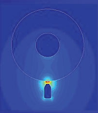
Figure 6. E-Field Color Contour Plot - No Insulation Shield near metal point.
The idea I’m trying to get across here is that cables or accessories with missing or even partially damaged semicon or metallic shields may experience very high and possibly damaging electric fields. Since air breaks downs above about 3 kV/mm at power frequencies, the field seen just outside the insulation in Figure 6 would cause local discharge. Modern, newly manufactured polymeric insulation may withstand 50 to 60 kV/mm at power frequencies, as long as the field is confined within the insulation. With age and under different environmental conditions, insulation will deteriorate, and will break down at considerably lower magnitude.
Final results of a Failure
A cable failure almost always exhibits itself as either an open circuit or a short circuit. Open circuits are more common in low voltage cables than at medium or high voltage. Open circuits are usually the result of failed connectors, or broken and/or corroded conductors. The reason that open circuit failures are rare in higher voltage systems is that arcing will occur in the conduction path, leading to overheating, failure of the insulation and a short circuit.
From now on I will concentrate on short circuit failures. Short circuit failures will most often cause the protection system to operate and interrupt the current flow to the load. There are times when the flash over at the fault may result in more serious consequences like fire or even explosion.
Root Cause Failure Analysis
Root cause failure analysis is the process of examining a failed sample, along with the operating and environmental information, to determine the fundamental cause of the failure. During the failure analysis, various tests may be conducted on the failed sample, on pieces of nearby unfaulted cable, or on accessories removed from adjacent un-failed phases. Each bit of evidence is looked at as an effect, which had a cause. Then each cause is looked at in turn as the possible effect of a previous cause. This cause/effect trail is followed to the fundamental or root cause.
The amount of evidence that can be gathered will depend on the condition of the sample, what has happened to the sample since the failure, and the availability of information about the failure and previous conditions that the cable or accessory has undergone. Often direct evidence at the failure site is destroyed by the fault. An important factor in failure analysis is of course the amount of time and money one can spend on the analysis.
In this short article I cannot hope to cover all aspects of failure analysis. That would take a book. What I hope to cover are some of the things to look for and some of the tests that may be used in a failure analysis. I will attempt to illustrate the process by example.
Two important things that must be done in any failure analysis are a close visual examination of the sample at and near the failure site, and talking to or reading accounts of the failure from the personnel involved. Depending on the circumstances more investigations or tests may be required, or more information may be requested from the cable user.
If the failure occurred in a polymeric cable, other work may include:
- More detailed examination of the conductor including possible metallurgical examination
- Dissecting the insulation close to the failure and cutting wafers
- Measuring insulation resistance
- Performing ac breakdown level tests on a long sample near the failure site
- Performing chemical tests on the insulation
- Measuring semicon resistivity at elevated temperature near the failure site
- Performing metallurgical tests on the shield or sheath if present
- Performing chemical tests on the jacket if present
During the examination, look for signs of overheating. These may include discolored metal, or cracked and distorted polymers. Figure 7 shows an embrittled and cracked polyethylene wafer caused by overheating. Remember to look at samples sufficiently far from the fault site to be sure they were not damaged by the arcing fault. Overheating may indicate a possible root cause of failure of the system protection, incorrect determination of the system ampacity, thermal runaway, or lack of thermal backfill. Signs of over heating may warrant further chemical or metallurgical tests to determine the maximum temperature reached. Further investigation into system operations may be necessary to determine the true root cause of this type of failure. Examples of root causes of over heating may be poor initial ampacity calculations, improper breaker settings, removal of proper backfill, or change in ambient conditions like the adding of a steam pipe.
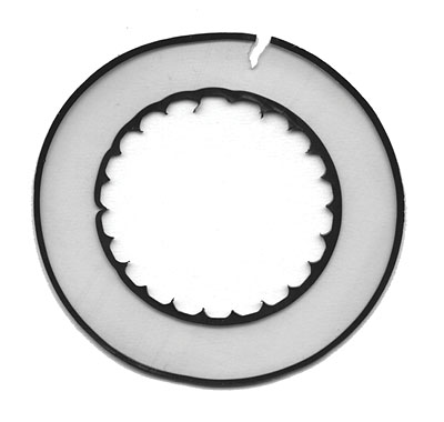
Figure 7. Cracking of embrittled insulation.
Voids or inclusions in the insulation, or protrusions from the semicon may be seen in the wafer examination. Figure 8 shows a cable wafer with extensive voids. Voids are simply bubbles in the insulation, while inclusions are foreign matter. Protrusions are sharp points extending into the insulation from the semicon. These are all forms of cable manufacturing defects. All cause high local e-fields, which may lead to partial discharge at the site or rapid growth of water or electrical trees near the defect. Any of these observations indicate a manufacturing defect as the cause of failure. Unfortunately the defect, which may have caused the failure, is usually destroyed by the fault, but the presence of nearby defects may give sufficient evidence of poor manufacturing. Since modern cables can be produced with super-clean insulation and semicons, and very few defects, one might conclude that the root cause of these types of failures occurring in newly purchased cables is poor specifications or acceptance testing.
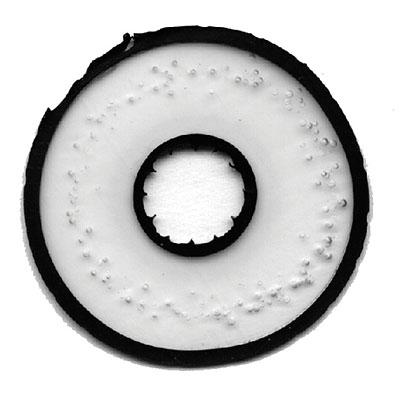
Figure 8. Cable wafer with extensive voids
Water trees can grow in both polyethylene and EPR insulation. Figure 9 shows a large vented water tree growing from the insulation shield. This water tree has a fault through it. Figure 10 shows a cable with a forest of water trees, which can be seen without dissecting the insulation. Water trees require both moisture and an electric field in the insulation to grow. If the cable is an older design made and installed before or about 1980, and has extensive water tree growth, one may conclude that the root cause of failure is simply that the cable has reached its normal endof- life. If newer TR-XLPE has extensive water treeing, a manufacturing problem may be the cause. If the cable is supposed to have strand blocking, water absorbing tape, or a hermetically sealed LC shield, and develops extensive water treeing in a short time, investigate the possible root cause as a manufacturing problem, mechanical damage or shield corrosion.
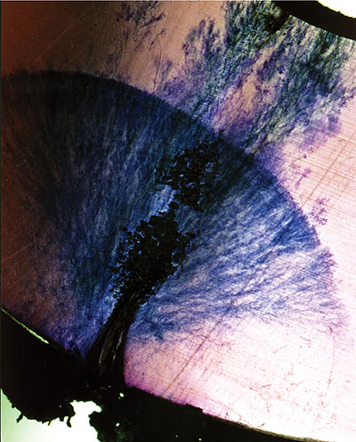
Figure 9. Large vented water tree at a fault site.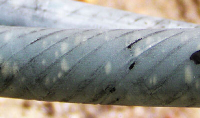
Figure 10. XLPE cable with a forest of water trees
Another type of failure is evidenced by signs of burning or arcing on the surface of the semicon. If the burning or arcing becomes extensive, the cable can fail from the outside in, as seen in Figure 11. The cause was determined to be a damaged jacket, which led to corrosive ground water entering the cable and causing severe corrosion of the metallic shield.
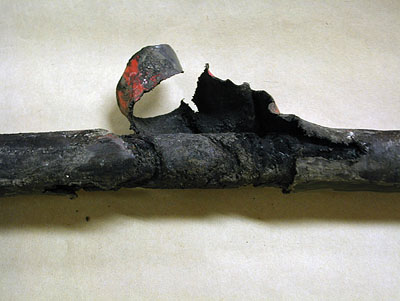
Figure 11. Cable failing from the outside in
Compounding the problem of a damaged metallic shield can be high resistivity in the semicon insulation shield. The volume resistivity of the semicon in older cables often increased with elevated temperatures. This effect was demonstrated in the lab as shown in Figure 12. Figure 12a shows a break made in the taped metallic shield. In Figure 12b, the conductor was energized and carrying current. As the current was increased the cable temperature rose. At about 50º C, the semicon resistivity had increased to the point where arcing took place across the break in the metallic shield.
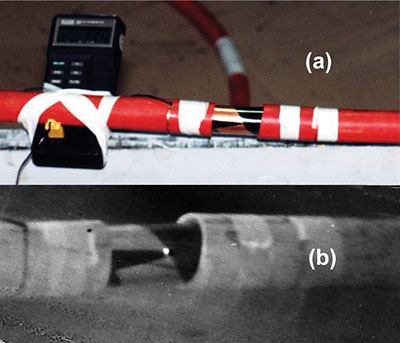
Figure 12. Lab test showing shield arcing due to elevated semicon temperature
To investigate a failure in an accessory, in addition to the usual visual examination and gathering of environmental and operating information, other work specific to accessory failure analysis may include:
- Comparing the failed accessory with undamaged accessories in adjacent phases
- Measuring contact resistance in connectors
- Careful dissection of the accessory comparing dimensions with assembly drawings
- Looking for signs of poor workmanship
- Looking for signs of surface tracking
- Looking for electrically floating metal electrodes.
Problems in connectors are a common cause of accessory failure. Figure 13 shows a drawing of a load-break separable insulated connector (SIC). Within the elbow, bushing insert, and bushing well that make up the SIC, there can be up to eight electrical contacts. Usually problem connectors overheat, which is evidenced by a discolored or burned conductor or insulation. Root cause of the failure is often improper installation including bad connector crimps, cross threading of the elbow probe, or a broken stud in the bushing well. Some older load-break SICs had design flaws in the contacts in the load break mechanism.
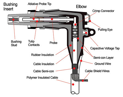
Figure 13. Elbow and Bushing Insert Drawing
Figure 14 shows an XLPE cable end, which was removed from a failed pre-molded splice. The results of arcing can be seen on the insulation surface. When the installer penciled the insulation, burrs were left on the end of the insulation and the surface was very roughly sanded. When the insulation was inserted into the splice body, semicon material was dragged over the surface. The semicon material led to surface tracking and eventual flashover. The cause of the failure was poor workmanship. One might conclude that the root cause is poor training, installation processes or standards.
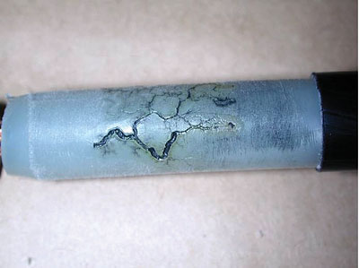
Figure 14. Poor Workmanship Leads to Failure in Pre-molded Splice Installation
Summary
Determining the root cause of a cable failure can lead to better maintenance practices, produce more reliable operation, and lower operating costs. Root cause analysis requires a systems approach, which includes understanding the cables, their accessories and operating environment. ¦
ABOUT THE AUTHOR
Vern L. Buchholz, P.Eng. After completing his Bachelors degree, Mr. Buchholz worked for 7 years as a research associate at the University of British Columbia, Vancouver, Canada, designing television systems for remote sensing. He joined BC Hydro in 1981 performing electrical design work on overhead and underground transmission systems. He came to Powertech Labs Inc., a research and testing subsidiary of BC Hydro, in 1984 were he is now the Director of the Electrical Technologies Business Unit. His group’s major work covers power cable and large generator and motor testing, and operation of the High Current Lab. He is a Senior Member of the IEEE, and is a member and chairman of a number of standards working groups under the Insulated Conductors Committee. He is a Professional Engineer registered in the Province of British Columbia Canada.