
Robotic technologies are an innovative way to assist utilities in their asset management programs. The Electric Power Research Institute (EPRI) is developing robots that will inspect transmission lines and insulators for overhead transmission lines.
A Robot for Transmission Line Inspection
Overhead transmission lines are among the utility industry’s most widely distributed assets. In the U.S. alone high-voltage lines run more than 150,000 miles, often in remote locations. Reliability requirements, component aging, clearance and right-of-way inspection compliance drive the need for thorough, timely inspections along the entire length of these lines. Such comprehensive assessments by maintenance personnel, working on the ground or in aircraft, currently entail significant expense.
To expand inspection capabilities and increase cost-effectiveness, EPRI is developing a transmission line inspection robot that can be permanently installed on these lines, and traverse 80 miles of line at least twice a year, collecting high-fidelity information that utilities can act on in real time. As the robot crawls along the transmission line, it uses various inspection technologies to identify high-risk vegetation and right-of-way encroachment, and to assess component conditions.
After an initial concept design, the EPRI research team refined the design and developed a prototype robot. Nicknamed ‘Ti,’ EPRI has put the prototype through a series of tests at its laboratory in Lenox, Massachusetts and is compiling data that will lead to further refinement of the design.
Features and Functionality
Ti uses high-definition visual and infra-red spectrum cameras with advanced image processing to inspect the right-of-way and component conditions. It will be able to determine clearances between conductors, trees, and other objects in the right-of-way. The cameras also will be able to compare current and past images of specific components to identify high-risk conditions or degradation. As an alternative to the camera, the robot may be equipped with a Light Detection and Ranging (LiDAR) sensor to measure conductor position, vegetation, and nearby structures.
Ti will transmit key information to utility personnel, with a global positioning system accurately identifying its location and speed. Another system will collect data from remote sensors deployed along the line, and an electromagnetic interference detector will identify the location of discharge activity, i.e. corona, or arcing. Where discharges are identified, field personnel may do further inspections using daytime discharge cameras.
The conductor-crawling robot has been designed to work with a variety of EPRI-developed radio-frequency sensors that can be placed along transmission lines to provide real-time assessment of components such as insulators, conductors, and compression connectors. These sensors will likely be deployed in areas of environmental stress or where specific component types have been installed. For example, lightning sensors will be installed in high-lightning areas, vibration sensors will be used in high-wind areas, and leakage-current sensors will be deployed in coastal areas to detect salt contamination.
The deployed sensors will collect data continuously, develop histograms, and determine maximum values. Data will be transmitted to Ti when it is in close proximity and will then be transmitted to maintenance personnel. The inspection robots, when coupled with these sensors, will be able to provide comprehensive, accurate, and useful information to optimize line maintenance and improve transmission reliability. In some cases, the purchase of robots for use in place of maintenance crews could shift O&M expenses to capital costs, allowing a return on investment and depreciation.
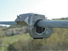
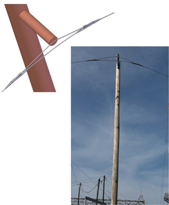
In the field, the transmission line robot will be permanently installed on a transmission line shield wire. It traverses structures and obstacles, e.g. marker balls, utilizing bypass systems that are permanently installed on the transmission line. The robot automatically disconnects itself from the shield wire and connects itself to the bypass system. Once it is has bypassed the obstacle or structure it then returns to the shield wire. These bypass systems could be installed during construction or be made integral to the line hardware. It is envisioned that the robot’s mobility could be developed to remove the need for by-pass systems, enabling its deployment on existing transmission lines.
Although Ti may be permanently installed on long transmission lines it can be relocated if required to other transmission lines or it may move from one line to another utilizing a bridge that is installed on nearby structures.
The current version of the robot is designed to inspect an average of 12 765kV structures and spans per day. It is capable of moving up to five miles per hour if it needs to reach a portion of the line more quickly, for example to inspect a line outage. The robot draws energy through power harvesting and stores it in onboard batteries.
Stages of Transmission Line Robot Development
This research, development and demonstration project began in 2008 and is targeted to result in a field implementation in 2014.
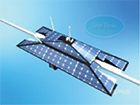
Concept – Initial requirements for the robot developed based on industry knowledge and feedback from utilities. The bypass system, solar panels, sensor package and power requirements were a key emphasis in the concept development design.
Design – A detailed design was performed of both the robot and the bypass systems. Details of mobility as well as the integrated sensor, control and communications package were developed.
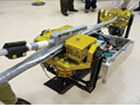
Technology Demonstration – Technology demonstrators of both the bypass systems and the mechanical components of the robot were constructed, tested and refined. Testing was performed on indoor short sections of line with bypass systems installed.
Full Scale Laboratory Testing – A test loop was developed where all the challenges that the technology demonstration robot would encounter on a typical 765kV line were simulated (angles and inclination). Bypass systems were developed for each of the challenges, and then refined and installed. The robot was then tested and evaluated as it faced each of the challenges.
Remote RF Sensor – A suite of RF integrated sensors has been developed to continually assess the condition of components and transmit to Ti when it is in close proximity. Leakage current, conductor temperature, vibration, lightning and fault sensors have been developed and are currently being demonstrated at 12 sites.
Bypass System – The Heart of the Technology
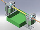
One challenge in developing the robot was to create a design that would enable it to move along the shield wire of transmission lines and move past a structure or other obstacles in its inspection path. Ti utilizes bypass systems that are permanently installed on the structure and around objects.
EPRI is testing six systems that will use an additional short section of shield wire by which the robot can bypass the tower structure and other obstacles with no operator input as it makes its way to the next line section. These may be in addition to the normal line hardware or built into the normal line hardware.
For new transmission lines the cost of the additional or modified hardware is negligible compared to the overall cost of the transmission line.
Development of Test Site
To validate the robot’s and bypass systems’ performance, EPRI constructed a test site at Lenox, MA. This ‘Loop’ simulates the most challenging situations that the robot would encounter on a 765kV transmission line shield wire. A range of angles and inclination combinations as well as different configurations were designed into the Test Loop.
Review of Ti Robot Performance and Findings
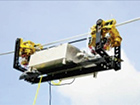
Mobility: A robot and a bypass system test area have been built and undergone a series of tests both indoors and on the Loop. The technology demonstration robot was able to navigate all of the challenges of the test loop multiple times without operator input. Important insights were obtained that will result in design improvements, and researchers gathered data on power usage and battery performance.
Sensor Package: A suite of four remote RF sensors from which the robot will collect data are being tested at 12 utility sites ranging from 138kV to 345kV. These tests will result in new improvements and developments for the robot. Initial test results of the LiDAR sensor show great promise. Below is an example of an image generated by this sensor.
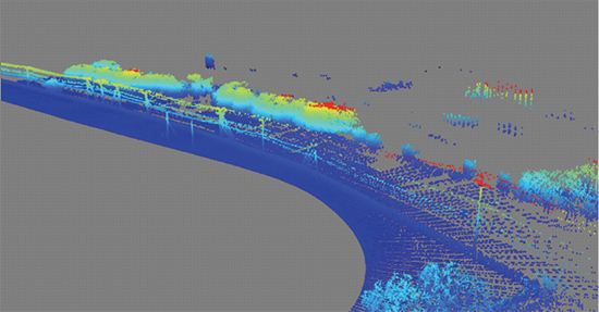
Colors represent the height above ground – the LiDAR measured the distance from the robot using the laser,
then with the knowledge of the location works out the height of the objectives above ground.
A detailed sensor and control system architecture has been developed and is currently being implemented. It will be tested and then finally integrated into the robot itself.
Next Steps in Development
Using knowledge from the loop testing, the next generation of robot and bypass systems is being designed and implemented.
In 2011 a third round of successful testing was completed. A range of new features and revisions were tested on the technology demonstrator to assess their performance and lay the ground work for the design and development of the first prototype unit. Ti circled the test loop at EPRI’s Lenox, MA laboratory over 200 times in a row showing the long term feasibility of the concept. In addition, initial LiDAR and high definition camera testing was completed on the test loop. An electronics package and control system for the robot was developed in 2011 and bench tested.
A vendor has been engaged to commercialize the line hardware for the diverter and bypass systems. Work is underway to integrate this hardware with their existing product line.
Based on the results of testing the first prototype unit has been designed and is presently being constructed. The unit is expected to be tested in the late summer of 2012.
EPRI is working with American Electric Power (AEP) engineers to include the robot and bypass systems on a 138kV transmission line to be refurbished in 2014.
Another Robot for Inspecting Transmission Insulators
As transmission line assets age, utilities are challenged on how to address an aging population of composite and porcelain insulators. An important part of the decision making process is to determine the condition of the present population in-service so that one can determine whether to extend life or replace. In addition it is important for field personnel to evaluate the condition of insulator string prior to performing live work on a structure, even if the live work does not relate to the insulators. The issue is more challenging for composite insulators where limited in-service inspection techniques exist.
Insulator Inspection Methods Today
Existing and emerging inspection technologies to assess the condition of transmission line insulators often require close proximity or contact with the insulator string. EPRI is developing a new inspection technology for composite insulators to evaluate their electrical integrity, which is known as the Live Working NCI Tool. The present version of this new technology design requires the utilization of a hot stick as does the application of hot stick camera technologies. At Extra High Voltage levels this is potentially challenging due to the length of the hot stick required and the impact on the operator. EPRI researchers identified this as an appropriate application for robotics as a transport mechanism for these inspection technologies.
A Robotic Solution
As a result of this need, EPRI initiated the development of an ‘Insulator Crawler.’ This robot would incorporate the Live Working NCI ‘detector technology’ and a video camera as a payload. In 2010, a feasibility study and a detailed design was completed, and in 2011, a technology demonstrator, nicknamed ‘Ike,’ was constructed and remotely tested on I-string, Vee-string, and dead-end de-energized insulators with success.
A camera and an EPRI prototype Live Working NCI Tool, which assessed the integrity of polymer insulators, was then integrated into Ike and tested. It showed very promising results with improved repeatability over measurements made by an operator using a hot stick. Although there is a long way to go on this challenging development, the project is revealing that the use of robotics in the future has significant advantages, including more repeatable measurements, addressing ergonomic issues and increasing safety by enabling personnel to be removed from energized situations.
Features and Value
The insulator robotic technology can enable the implementation of existing and emerging close-proximity as well as contact insulator inspection technologies at EHV voltages, (EHV=extra high voltages 345kV and above). It could lead to a much better evaluation of the insulator and allow the utility to remove the operator from close proximity to energized conductors, leading to increased safety. It can also help to reduce the physical stress on operators, since they would not be required to use a heavy, long hot stick which places significant loads on the operator.
Next Steps in Development
In 2012 the capabilities of the Ike robot are being extended with the implementation of mechanical, automation and control improvements. A fully energized test in the laboratory environment is planned by the end of the year.
Recently, the development team conducted indoor lab tests on a new version of the transmission line robot. The new prototype robot is based on the numerous lessons learned with the original Technology Demonstrator that was tested for over two years on the outdoor field test loop in Lenox, the transport system wheel tester, and in the lab. The prototype robot has a fully integrated control, communication, and power system and various sensor systems have been fully integrated into its design, including LiDAR, High Definition video, still images, infrared camera, EMI detector and a weather station. The battery system is now fully integrated into the design.
A new set of prototype line hardware has been developed by a commercial vendor based on their current product offering. The new mechanical design of the robot has evolved based on what was learned from prior tests and addresses this new line hardware design. A new series of outdoor tests are planned for the robot and new line hardware in October 2012. The testing will address robot mobility, control and command operations, communication, and sensor integration.
About the Author
 Dr. Andrew Phillips is Director of Transmission and Substation Research. Currently, his research focusses on the Overhead Transmission, Underground Transmission, Increased Power Flow, Substations, and high-voltage direct current (HVDC) programs. His special areas of interest are non-ceramic insulators (NCI), lightning and grounding, inspection and assessment of components, sensor development, and daytime corona inspection. Andrew received Bachelor of Science, Masters, and Doctorate degrees in electrical engineering the University of the Witwatersrand in Johannesburg, South Africa.
Dr. Phillips holds four U.S. Patents and is the author of over sixty journals and conference publications. He is a registered professional engineer (PE) and a member of the IEEE and CIGRE. He can be reached at aphillips@epri.com.