
The Smart Grid is about serving the customer better. It gives electricity consumers options to manage and optimize their energy usage. But to really serve the customer better, utilities also need to identify ways to improve the reliability of their electrical service. While it's impossible to prevent power outages, how the power system responds to these events determines how many customers are affected and for how long. High reliability can be designed into the distribution system - and the Smart Grid can help get us there.
Many different sources handle power generation in various locations, so end-users don’t notice the loss of a generator. The transmission grid intertwines with backup lines and multiple routes for power flow to handle contingencies. Therefore, an alternate route usually can accommodate the loss of a transmission line. In contrast, many parts of the distribution system – the source of most end-user interruptions – aren’t really a grid at all. And they don’t have any level of backup. So, customers are susceptible to a power outage on the distribution system even when it occurs several miles away.
A basic distribution grid develops when utilities add the capability to transfer loads to adjacent circuits. A smart distribution grid emerges when the switching points between circuits, as well as several points along each circuit, carry the intelligence to reconfigure the circuits automatically when an outage occurs and quickly to reroute power to as many customers. More intelligent switching points yield more options to reroute power to serve the load, and communication between those points makes selfhealing a practical reality.
Alternate routes, multiple switching points and communications can also help minimize power losses and manage peak loads. Further, an automatically reconfigurable distribution grid requires flexibility to accommodate the anticipated escalating levels of distributed generation and energy storage. Distributed generation comes and goes unpredictably, a dynamic activity that won’t work in the traditional form of a radial circuit on a distribution system.
Smart Grid Favors New Technologies
The Smart Grid is a global effort to improve the delivery of electric power. It is backed and driven by national governments with set goals and requirements for the industry. They have invested billions of dollars to foster and forge new projects to demonstrate the advantages of fresh technologies. As such, Smart Grid favors the employment of new technologies to move the industry forward. It is not simply using “more of the same.” While this focus strives to deliver better system performance, it also seeks to provide social benefits that include reduced carbon emissions, financial benefit for utilities and better service for customers.
Companies offering Smart Grid solutions range from startups with a single new idea to global giants preparing to integrate communication systems, operation systems and back office IT infrastructure. In the future, the Smart Grid will employ an intelligent, networked distribution system to operate new applications that don’t even exist today. Pioneer technologies will integrate renewable energy sources and use energy-storage devices to make renewable-source energy dispatchable. Power distribution systems will undergo the most rapid transformation and will rely on innovative products and technologies.
Distribution System Response to Faults – The ‘Regular Grid’ Version
When a fault occurs on the distribution system, it is interrupted and cleared by a fuse, recloser, or relayed circuit breaker. If the fault is cleared by a fuse, the utility must send a crew to patrol the line, locate and repair the fault, if necessary, and then replace the fuse to restore service. On many occasions – studies suggest between 60 percent and 90 percent of the time – faults are temporary by nature, and would actually dissipate if given a short period of time with the system de-energized. But, a fuse is a one-shot device and once it melts to clear the fault, a permanent outage results for the downline sections until service is restored by the line crew.
An improvement in the 1940s came when reclosers and reclosing relays offered a dual-timing characteristic. The recloser or relay is set to trip faster than the fuse, and then wait a few seconds before it recloses. If the fault is temporary, it may be gone before the first reclosing attempt. This protection technique is known as fuse saving.
But fuse saving has some disadvantages. For one thing, electronically controlled devices required to measure fault currents and mechanically open contacts to interrupt the fault simply cannot perform this action as fast as a fuse link at high fault currents. Therefore, most faults on the system result in the recloser tripping and the fuse blowing. This is actually worse than not trying to save the fuse because the fuse blows and all customers downline of the recloser experience a momentary interruption.
Another downside is that a typical implementation uses two or three reclosing attempts. If the fault is permanent by nature, each reclosing attempt re-ignites the short circuit. Then full-magnitude fault current flows through the distribution conductors, switches, splices, and perhaps most importantly of all, the substation transformer. This causes undue thermal and mechanical stress on all the system components. It leads to eventual failures of splices or other weak points on the system and reduced service life for the substation transformer. Also, each time the fault is re-applied to the system by reclosing, the feeder voltage is pulled down, and upline customers experience power quality issues.
Pulseclosing: A High-Performance Fault Interrupter
Fortunately, a new and better alternative has emerged to reclosing and it is called pulseclosing. It is the first major advancement in the power-handling aspects of fault isolation since reclosing was introduced. In time, it may become the new fault-testing standard. After a conventional recloser or relayed circuit breaker opens to interrupt a fault, it typically recloses into the fault several times to determine if the fault is still present.
Pulseclosing, though, tests whether the fault is still present without creating high-current surges that cause feeder stress. The pulsecloser very rapidly closes and re-opens its contacts at a precise point on the waveform to send a very short low-current pulse down the line, then analyzes the pulse to determine the next course of action. If the pulse indicates a persistent fault, the pulsecloser will keep the contacts open, wait a userconfigurable interval, and pulse again. This process can repeat several times until the pulsecloser determines that the line is no longer faulted. It then closes to restore service. If the fault persists for the duration of the test sequence, however, the pulsecloser will lock out to isolate the faulted section.
Pulseclosing uses very fast (i.e., about one- or two-milliseconds) closing and opening of the main switchgear vacuum-interrupter contacts. This controlled point-onwave closing limits peak pulse current to about half the expected symmetrical fault current that would have occurred with a hard reclose into the fault. Pulseclosing uses fault asymmetry to its advantage because the first current loop is the much smaller minor loop. It then interrupts the current before the major loop occurs.
Current flows from contact touch until the next current zero, typically resulting in a pulse current of about 5-ms duration. This very fast mechanism hits the point-on-wave closing target and then quickly reverses momentum to open the contacts.
A software algorithm analyzes the pulse based on the point-on-wave closing angle, pulse magnitude, and length and shape of the pulse to project what the current flow would be if the contacts were fully closed. If the predicted current flow indicates load current instead of fault current, the switchgear contacts will close less than 100 ms after the pulse.
Pulseclosing does not stress power system equipment, typically reducing energy let-through by more than 98 percent compared to the energy associated with a hard reclose. It also reduces the peak fault current forces on transformer windings by up to 96 percent compared to a hard reclose. (See Figures 1 and 2, following)
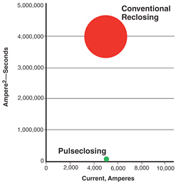
Figure 1. Relative let-through energy for a typical 5000-ampere fault
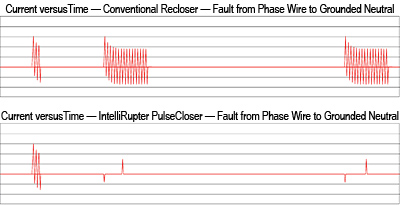
Figure 2. Oscillographs showing the difference in fault current for a hard reclose
and a pulseclose on a permanent phase-wire to grounded-neutral fault
After clearing a fault, a conventional recloser or relayed circuit breaker simply recloses to test for continued presence of the fault. If the fault persists, its control compares the current to a Time Current Characteristic curve, and trips the interrupters at the appropriate time. After a time delay, it recloses again. Even the fastest recloser or breaker feeds a significant amount of energy into the fault with each reclose, producing system-damaging stress and voltage sags.

Figure 3. Conventional reclosing in response to a permanent fault
Figure 3 shows how a conventional recloser or relayed circuit breaker operates in response to a permanent single-phase-to-ground fault. The uncontrolled closing often results in asymmetric fault current, significantly increasing peak energy into the fault.
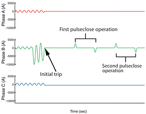
Figure 4. Pulseclosing in response to a permanent fault
When the pulsecloser clears a fault, however, it tests for continued presence of the fault using pulseclosing technology, closing at a precise point on the voltage wave. Figure 4 shows the typical current pulse of just 5 milliseconds; the system only experiences overcurrent stress from the initial fault.
The opposite-polarity pulse detects magnetizing inrush current; if the line is not faulted, the pulsecloser closes to restore service.
Automatic Self-healing for the Distribution Grid
The distribution system is the electrical link between meters (smart or not) and the transmission grid. Industry experts estimate that 80 percent of customer outages result from problems on the distribution system, which largely consists of utility poles along roadways and in alleys, or underground cables commonly found in newer subdivisions or business areas. The self-healing part of Smart Grid is a critical element for the distribution system.
Self-healing technology enables automated switching devices on the distribution system to reconfigure the circuits automatically to restore power to as many customers as possible and isolate only the problem section of the line. To accomplish this, automatic switch controls are deployed on the distribution system, and programmed with automatic restoration logic.
The optimal self-healing system will use a mix of decentralized fast-acting local response with a centralized system for oversight. Local clusters of automated feeders function independently of the central control to isolate problem areas and minimize disruptions quickly. The feeders may be in a reconfigured state for several hours until the crews have located and repaired the fault, so the distribution operators may want to shift load, switch capacitors banks, or modify voltage regulation to optimize efficiency.
Distributed logic also will handle multiple events. With such logic, no need exists to pre-script switching scenarios for multiple-fault contingencies. Distributed logic only requires a very simple, first-time setup, and regardless of how many events have already occurred, it will continue looking for alternate sources to restore the unfaulted sections that are without service. This is especially useful during strong storms that sweep across a service territory and cause multiple outages. It’s a great advantage to have the distribution system automatically do the best restoration possible, quickly and efficiently, and report the final reconfigured state to the dispatchers.
High-Speed Communications Infrastructure
The industry is quickly moving toward a distribution system that monitors, records, and reports more and more data through the SCADA, “supervisory control and data acquisition,” system as intelligent controls and sensors become more widespread. AMI (for advanced metering infrastructure) traffic alone requires an upgraded and expanded communication system to handle the data volume. Performance of a distribution automation system using self-healing technology depends heavily on the communication system.
A high-bandwidth radio system is advantageous today, and becoming more critical with every new technology advancement. It enables remote management functions, such as the ability to upgrade radio firmware over the air, or even update the firmware in the switch controls. The capability to remotely retrieve event log and waveform data and remotely make configuration changes saves time and expense, as well as reduce carbon emissions associated with crew and truck travel.
Mesh topology is important because it allows switching devices in the field to communicate directly with each other, rather than to the neighbor control via a convoluted process that requires routing through the SCADA Master.
For applications where speed of communication is important, the mesh network offers a superior design. Redundant alternate paths are inherent in the mesh network approach, so if one or more preferred communication links is down, the mesh network uses any nearby radios as repeater stations to reroute messages quickly and reliably to the appropriate switch location, or even back to the operations center. The ability to route automatically around a missing node provides another example of a selfhealing system that increases the robustness of the distribution system.
Reliability of the grid will gain even more focus as AMI deploys. Customers will have greater access to outage and other service-disruption data. Automatic self-healing technology that leverages the distributed intelligence of smart switching devices and a robust, high-speed, mesh communication system will get the lights back on quickly.
 About the Author
Christopher A. McCarthy is product manager for the Automation Systems Division of S&C Electric Company in Chicago, Illinois. Chris has participated in R&D, marketing, and field application support for the rollout of the company’s lines of smart switching and communications solutions and is now responsible for customer service, application support, and marketing for all automation products. He received a BSEE from the University of Illinois at Champaign-Urbana; a Masters in Electric Power Engineering from Rensselaer Polytechnic Institute, in Troy, New York; and an MBA from Keller Graduate School of Management. He is a registered Professional Engineer in the state of Wisconsin.