Background
A Medium Voltage (MV) Subcycle Static Transfer Switch is a solid state unit which is capable of switching large amounts of power, for example up to 40 MVA at 38kV, in less than 1/4 of a 60 Hz cycle or 4.17 mSec. They are available across a medium voltage service range of 5kV to 38kV and with currents up to 1400A. This type of switching differs from the conventional method of mechanical switching in that the static transfer switch does not result in an open transition to the load; this prevents heavy in-rush currents resulting from transformers magnetizing, motor starting, etc. Conventional, mechanical, transfer switches require an open transition between the sources so as to avoid paralleling of the sources. While it may be possible to parallel utility sources, often times requiring utility permission, it is only desirable if the two sources are at the same nominal voltage levels and in phase. This prevents a heavy load flow between the two sources due to voltage and/or phase differences. Normally a transfer is required when one of the sources, designated as the Preferred Source, is out of tolerance due to a total loss, reduced voltage, loss of a phase, etc. In this case, if the sources are paralleled, the deficient source can also result in the good source tripping due to an over-current or under voltage/phasing condition.
Moreover, a Subcycle Static Transfer Switch (STS) transfers between sources not only by appearing as an open transition to the sources but also as a closed transition to the load. While conventional mechanical switches use breakers or switches, which can be affected by ambient temperature, humidity, mechanical wear, the STS uses high power solid state thyristors (SCRs) to switch and conduct. These devices will not allow a reverse load flow to occur. This is illustrated in Figure 1.
The single-phase example in Figure 1 shows two thyristor pairs configured as a Form C switch. The switch on the left is conducting (Preferred Source) while the switch on the right is serving as the Alternate Source. When the Preferred Source voltage drops below a predetermined level, the sensing and controls in the switch will remove the gating signal to the left side thyristors. This does not turn the thyristors off. A thyristor cannot turn off until the current flowing through the device crosses zero. Applying the gate signal to the Alternate Source thyristors will turn them on. Since the Alternate Source is at a higher voltage, they will begin to conduct to the load. This higher voltage to the load will also force the Preferred Source thyristors off in a matter of microseconds. This is known as forced commutation, natural commutation occurs when the current sinewave crosses zero. No current will flow from the Alternate Source to the Preferred Source due to the blocking action of the off thyristor pair. A three phase switching event occurs in a similar manner with the thyristors in the Alternate Source commutating their opposite numbers in the Preferred Source off. This all occurs in less than 1/4 cycle and results in a smooth, near seamless, transition to the load.
The Static Transfer Switch and the Utility
Utilities have two levels of coordinated planning to consider regarding the application of STS units: engineering and system performance considerations, tariff and economic considerations.
Engineering
Normally, the utility will need to conduct load flow studies as well as stability and transient studies before adding a large amount of load switching. Open transition switching of loads in the MVA range can cause excessive voltage drops, raise or lower system frequencies, and result in false tripping of upstream protective devices.
When large MVA loads are switched with alternative slower technologies such as a mechanical or ATS switch, an open transition results. The upstream utility distribution system and the downstream customer load will be impacted when the mechanical or ATS switching methodologies are used. Open transition mechanical of ATS switching can take several cycles at best. Existing customer loads will cause a large in-rush on the utility system as the customer transformers magnetize. If large motor loads are switched back on, a similar in-rush will result. Motors, which are still on line, may be out of step and attempt to slip poles as they get back into synchronization. Utilities can have similar problems with their system transformers but also with transmission lines recharging. If the alternate source is not stiff (good voltage regulation from no load to full load), this sudden increase or decrease in load can result in excessive voltage swings and generator frequency changes. This will impact all customers served by the source.
The soft switching which results from the closed sub-cycle static transfer switch transition is nearly transparent to the utility system or alternate source. The predominant concern for the utility is with the load flow. Do the two distribution sources, preferred and alternate, have the steady state capacity to handle the load? For example, if the alternate source has only 5 MVA available capacity remaining, the sub-cycle transfer switch cannot switch 10 MVA onto the source. Another consideration is the impact on system equipment such as upstream automatic tap changers and protection such as undervoltage relays located in the utility substation. When the load is switched to the alternate source, the voltage on the alternate source may sag. An upstream tap changer will attempt to compensate if the sag is low enough. If the STS transfers back quickly, in a few cycles, the tap changer and STS may chase each other. A short retransfer time delay will eliminate this problem. Since the transfer using a sub-cycle static transfer switch is a soft event, overcurrent events will be minimized but the settings of upstream protection may need to be evaluated. Undervoltage protection will likewise need to be evaluated to determine that the STS switching will not impact system operation.
To illustrate, Ford Motor Company has an electronics manufacturing plant located in West Point, PA, north of Philadelphia. The local utility is PECO Energy. A Silicon Power 38 kV switch operating at 33 kV and a full load of approximately 170A or 9.7 MVA supplies this plant. When this load switches to the alternate source, it is being supplied by a “soft source”, a line approximately 17 miles in length. The only impact, to the utility or to Ford, is the voltage drop of approximately 2.5% on the alternate source at the load. A tap-changing transformer, located in utility substations can correct this. This longer line is designated as the alternate source and can carry the load for short durations under emergency ratings. PECO Energy required no extraordinary measures to have this customer owned switch installed on their system. Only normal load studies were required to determine the impact of the switching. Moreover, switching of these lines is a “soft” switching event as there is no in-rush due to magnetizing loads, etc.
To demonstrate the impact of a switching event using a mechanical switch and a sub-cycle STS, a switching simulation was performed using PSCAD Software:
Figure 2 shows two “stiff” 162kV sources (as Thevenin Equivalents), supplying two identical transformers over 10kM transmission lines. The transformers are 162/13.2kV at 30MVA. The STS load is a single 13.2/0.48kV transformer supplying a mixed industrial load. Two scenarios involve a mechanical transfer switch with a 1-1/2 open cycle transition time and an STS with a 1/4 cycle transfer time. The simulation will be on a grounded system with a high impedance ground on the Preferred Source, a solid ground on the Alternate Source, and a high impedance grounded load. A single-phase fault to ground initiates the transfer.
Figures 3 and 4 show the impact of the switching event illustrated in Figure 2. Source 1 and Source 2 show the voltage and current at the input to the switch, Load shows the secondary values of voltage and current at the customer loads. Figure 3 shows the switching event with a mechanical switch having a 1-1/2 cycle open transition. Figure 4 shows the same switching with a static switch having a 1/4 cycle transition. The most obvious effect of the 1-1/2 cycle mechanical transfer is that the voltage and current to the load have been interrupted. This results in a large in-rush into the primary of the load transformer, shown in the Source 2 current. This in-rush is on the order of 12X full load current. The 1/4 cycle STS does not show this type of in-rush. The in-rush for the 1/4 cycle STS is on the order of 2X-3X and has minimal impact on the secondary voltage and current.
Tariffs and Economics
Utilities are normally governed by regulations or tariffs. De-regulation has changed how utilities conduct business but often times, the tariff environment still has an impact on how and what a utility does. The concept of premium power is a new one and is often not covered by the governing tariff or regulations. The utility has to make several assumptions regarding the installation of any new technology. How will this impact the load, the source and surrounding customers? Will more of this type of technology follow? If so, how will this impact my overall system?
To consider these issues, the actual application and function of an STS needs to be discussed. The purpose of installing an STS, from the standpoint of the customer, is to provide a source of clean, reliable, conditioned, and uninterrupted power to the customer’s facility to support mission critical manufacturing and/or data operations. The STS offers performance similar to that of a UPS but at a much reduced life-cycle cost. Since the STS can switch in 1/4 cycle, it can actually anticipate and eliminate power problems on the source, between the utility substation and facility, where 90% of the utility based power line disturbances are known to be generated. Utilities usually specify or control the settings on service entrance equipment. Normally, source transfer set points in an STS are set much higher than a mechanical switch and the response is much faster. A mechanical switch will often times respond when the voltage is very low and several cycle have passed. Since the mechanical switches are substantially slower than their silicon based STS counterparts, the set points on them tend to be set very low, thus providing a transfer only for a very deep voltage sag. This type of response will not give the end user the type of uninterrupted power required. Since STS units can transfer so fast and on small and potentially damaging power perturbations in the source, they can transfer to a clean source many times a minute if required. To take full advantage of the performance of an STS, the set points and response time are usually kept very small. This will allow the STS to transfer and re-transfer in a matter of cycles.
Utilities have two methods of providing power to a customers load. The first is by sizing the service and equipment for normal calculated loads. The second is for emergency conditions where the load can be increased above normal capacity for short durations. It is a good assumption that the mechanical switch will normally respond only to deep sags. A sag of this nature is normally assumed to be a precursor to loss of the service. These types of losses are rare. Under these conditions, the emergency rating of the alternate source will be invoked to allow the alternate source to supply the load. The alternate source need not be sized for continuous duty, as this type load duration will be rare. However, since the operation of the mechanical transfer switch is an open transition, the mechanical switch does not normally retransfer back to the Preferred Source upon restoration, unless the Alternate Source is out of tolerance. The retransfer is typically a manual operation initiated by the customer or equipment owner.
The impact of an STS differs substantially from that of a mechanical switch. Since the sources are programmed to transfer upon pre-defined IEEE, CBEMA, and/or customer specific conditions which relate directly to a specific mission critical load condition, the alternate source may need to have the same available capacity as the preferred source. The two sources, in particular the alternate, needs to have acceptable voltage regulation. The “stiffness” of the source (a stiff source may be defined as +/-5% regulation from no-load to full load) will impact the operation of the STS and impact other customers. The available capacity of the alternate source may be considered as reserve capacity and may not be available for use by another utility customer. However, since the STS can transfer quickly to the alternate source, it can also transfer back when the anomaly on the preferred source has passed. The STS can be programmed to wait a defined period of time, several minutes, for example, and then transfer back to the preferred source, assuming the preferred source has recovered. It is incumbent upon the utility to determine the probability of a transfer and the probable duration of the transfer. Based on this assessment, the utility can determine if it will operate under the emergency rating or the continuous rating of the distribution.
Tariff structure, usually in the new form of a premium power rate, will certainly be considered when the utility decides that it must set capacity aside. If capacity is not available in the local substations, new equipment must be added to support the reserve required. How this is to be added can be dictated by the tariff. Other considerations for the local utility may include: Can the transmission lines supplying the substation support another transformer and distribution? Is there a nearby secondary transmission line with capacity that can be used?
When a utility adds additional capacity, it may do so in increments, which exceed that of the utility customer that installed the STS. For example, a utility normally builds substations in 50 MVA increments but the customer requires only 10 MVA of alternate source. In this case, the customer may only be liable for the reserve capacity they require which will be tariffed as a premium power plan to the customer.
Conclusions
A sub-cycle static transfer switch is often used with existing UPS systems in existing installations to ensure high 9’s power quality for mission critical applications. For existing facilities, the STS has been shown to immediately remediate plant and data center lost downtime, operational interruptions, lost productivity and product damage.
ROI’s have been clearly demonstrated in typically less than 2 years. For new projects, the STS will provide the user a lower life-cycle cost alternative to UPS systems, without the growing and substantially complex environmental, costly periodic maintenance concerns, and comparatively short service life associated with this technology. The response of an STS factors faster than
a back-up diesel generator and will provide a seamless power transfer. The transfer appears to the user as a closed transition and to the utility as an open transition. This satisfies both parties, and is clearly superior to a mechanical or ATS transfer switch. The disadvantage of a sub-cycle static transfer switch is that the acquisition cost is higher than a mechanical or ATS switch, but in comparison, no maintenance is required making the 30 year service life substantially lower.
From an engineering standpoint, utility switching events are minimized as the load is transferred to the alternate source without the heavy in-rush associated with open transition mechanical switches. The utility need only determine that the capacity is available or made available on the alternate source, and may negotiate a premium power plan with the customer to make this reserve capacity available.
References
A Medium Voltage (MV) Subcycle Static Transfer Switch is a solid state unit which is capable of switching large amounts of power, for example up to 40 MVA at 38kV, in less than 1/4 of a 60 Hz cycle or 4.17 mSec. They are available across a medium voltage service range of 5kV to 38kV and with currents up to 1400A. This type of switching differs from the conventional method of mechanical switching in that the static transfer switch does not result in an open transition to the load; this prevents heavy in-rush currents resulting from transformers magnetizing, motor starting, etc. Conventional, mechanical, transfer switches require an open transition between the sources so as to avoid paralleling of the sources. While it may be possible to parallel utility sources, often times requiring utility permission, it is only desirable if the two sources are at the same nominal voltage levels and in phase. This prevents a heavy load flow between the two sources due to voltage and/or phase differences. Normally a transfer is required when one of the sources, designated as the Preferred Source, is out of tolerance due to a total loss, reduced voltage, loss of a phase, etc. In this case, if the sources are paralleled, the deficient source can also result in the good source tripping due to an over-current or under voltage/phasing condition.
Moreover, a Subcycle Static Transfer Switch (STS) transfers between sources not only by appearing as an open transition to the sources but also as a closed transition to the load. While conventional mechanical switches use breakers or switches, which can be affected by ambient temperature, humidity, mechanical wear, the STS uses high power solid state thyristors (SCRs) to switch and conduct. These devices will not allow a reverse load flow to occur. This is illustrated in Figure 1.
Figure 1
The single-phase example in Figure 1 shows two thyristor pairs configured as a Form C switch. The switch on the left is conducting (Preferred Source) while the switch on the right is serving as the Alternate Source. When the Preferred Source voltage drops below a predetermined level, the sensing and controls in the switch will remove the gating signal to the left side thyristors. This does not turn the thyristors off. A thyristor cannot turn off until the current flowing through the device crosses zero. Applying the gate signal to the Alternate Source thyristors will turn them on. Since the Alternate Source is at a higher voltage, they will begin to conduct to the load. This higher voltage to the load will also force the Preferred Source thyristors off in a matter of microseconds. This is known as forced commutation, natural commutation occurs when the current sinewave crosses zero. No current will flow from the Alternate Source to the Preferred Source due to the blocking action of the off thyristor pair. A three phase switching event occurs in a similar manner with the thyristors in the Alternate Source commutating their opposite numbers in the Preferred Source off. This all occurs in less than 1/4 cycle and results in a smooth, near seamless, transition to the load.
The Static Transfer Switch and the Utility
Utilities have two levels of coordinated planning to consider regarding the application of STS units: engineering and system performance considerations, tariff and economic considerations.
Engineering
Normally, the utility will need to conduct load flow studies as well as stability and transient studies before adding a large amount of load switching. Open transition switching of loads in the MVA range can cause excessive voltage drops, raise or lower system frequencies, and result in false tripping of upstream protective devices.
When large MVA loads are switched with alternative slower technologies such as a mechanical or ATS switch, an open transition results. The upstream utility distribution system and the downstream customer load will be impacted when the mechanical or ATS switching methodologies are used. Open transition mechanical of ATS switching can take several cycles at best. Existing customer loads will cause a large in-rush on the utility system as the customer transformers magnetize. If large motor loads are switched back on, a similar in-rush will result. Motors, which are still on line, may be out of step and attempt to slip poles as they get back into synchronization. Utilities can have similar problems with their system transformers but also with transmission lines recharging. If the alternate source is not stiff (good voltage regulation from no load to full load), this sudden increase or decrease in load can result in excessive voltage swings and generator frequency changes. This will impact all customers served by the source.
The soft switching which results from the closed sub-cycle static transfer switch transition is nearly transparent to the utility system or alternate source. The predominant concern for the utility is with the load flow. Do the two distribution sources, preferred and alternate, have the steady state capacity to handle the load? For example, if the alternate source has only 5 MVA available capacity remaining, the sub-cycle transfer switch cannot switch 10 MVA onto the source. Another consideration is the impact on system equipment such as upstream automatic tap changers and protection such as undervoltage relays located in the utility substation. When the load is switched to the alternate source, the voltage on the alternate source may sag. An upstream tap changer will attempt to compensate if the sag is low enough. If the STS transfers back quickly, in a few cycles, the tap changer and STS may chase each other. A short retransfer time delay will eliminate this problem. Since the transfer using a sub-cycle static transfer switch is a soft event, overcurrent events will be minimized but the settings of upstream protection may need to be evaluated. Undervoltage protection will likewise need to be evaluated to determine that the STS switching will not impact system operation.
To illustrate, Ford Motor Company has an electronics manufacturing plant located in West Point, PA, north of Philadelphia. The local utility is PECO Energy. A Silicon Power 38 kV switch operating at 33 kV and a full load of approximately 170A or 9.7 MVA supplies this plant. When this load switches to the alternate source, it is being supplied by a “soft source”, a line approximately 17 miles in length. The only impact, to the utility or to Ford, is the voltage drop of approximately 2.5% on the alternate source at the load. A tap-changing transformer, located in utility substations can correct this. This longer line is designated as the alternate source and can carry the load for short durations under emergency ratings. PECO Energy required no extraordinary measures to have this customer owned switch installed on their system. Only normal load studies were required to determine the impact of the switching. Moreover, switching of these lines is a “soft” switching event as there is no in-rush due to magnetizing loads, etc.
To demonstrate the impact of a switching event using a mechanical switch and a sub-cycle STS, a switching simulation was performed using PSCAD Software:
Figure 2 shows two “stiff” 162kV sources (as Thevenin Equivalents), supplying two identical transformers over 10kM transmission lines. The transformers are 162/13.2kV at 30MVA. The STS load is a single 13.2/0.48kV transformer supplying a mixed industrial load. Two scenarios involve a mechanical transfer switch with a 1-1/2 open cycle transition time and an STS with a 1/4 cycle transfer time. The simulation will be on a grounded system with a high impedance ground on the Preferred Source, a solid ground on the Alternate Source, and a high impedance grounded load. A single-phase fault to ground initiates the transfer.
Figure 2: 1/4 Cycle Static Transfer Switch
Figures 3 and 4 show the impact of the switching event illustrated in Figure 2. Source 1 and Source 2 show the voltage and current at the input to the switch, Load shows the secondary values of voltage and current at the customer loads. Figure 3 shows the switching event with a mechanical switch having a 1-1/2 cycle open transition. Figure 4 shows the same switching with a static switch having a 1/4 cycle transition. The most obvious effect of the 1-1/2 cycle mechanical transfer is that the voltage and current to the load have been interrupted. This results in a large in-rush into the primary of the load transformer, shown in the Source 2 current. This in-rush is on the order of 12X full load current. The 1/4 cycle STS does not show this type of in-rush. The in-rush for the 1/4 cycle STS is on the order of 2X-3X and has minimal impact on the secondary voltage and current.
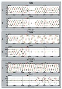
Figure 3: 1-1/2 Cycle Static Transfer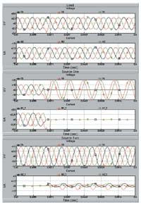
Figure 4: 1/4 Cycle Static Transfer
Tariffs and Economics
Utilities are normally governed by regulations or tariffs. De-regulation has changed how utilities conduct business but often times, the tariff environment still has an impact on how and what a utility does. The concept of premium power is a new one and is often not covered by the governing tariff or regulations. The utility has to make several assumptions regarding the installation of any new technology. How will this impact the load, the source and surrounding customers? Will more of this type of technology follow? If so, how will this impact my overall system?
To consider these issues, the actual application and function of an STS needs to be discussed. The purpose of installing an STS, from the standpoint of the customer, is to provide a source of clean, reliable, conditioned, and uninterrupted power to the customer’s facility to support mission critical manufacturing and/or data operations. The STS offers performance similar to that of a UPS but at a much reduced life-cycle cost. Since the STS can switch in 1/4 cycle, it can actually anticipate and eliminate power problems on the source, between the utility substation and facility, where 90% of the utility based power line disturbances are known to be generated. Utilities usually specify or control the settings on service entrance equipment. Normally, source transfer set points in an STS are set much higher than a mechanical switch and the response is much faster. A mechanical switch will often times respond when the voltage is very low and several cycle have passed. Since the mechanical switches are substantially slower than their silicon based STS counterparts, the set points on them tend to be set very low, thus providing a transfer only for a very deep voltage sag. This type of response will not give the end user the type of uninterrupted power required. Since STS units can transfer so fast and on small and potentially damaging power perturbations in the source, they can transfer to a clean source many times a minute if required. To take full advantage of the performance of an STS, the set points and response time are usually kept very small. This will allow the STS to transfer and re-transfer in a matter of cycles.
Utilities have two methods of providing power to a customers load. The first is by sizing the service and equipment for normal calculated loads. The second is for emergency conditions where the load can be increased above normal capacity for short durations. It is a good assumption that the mechanical switch will normally respond only to deep sags. A sag of this nature is normally assumed to be a precursor to loss of the service. These types of losses are rare. Under these conditions, the emergency rating of the alternate source will be invoked to allow the alternate source to supply the load. The alternate source need not be sized for continuous duty, as this type load duration will be rare. However, since the operation of the mechanical transfer switch is an open transition, the mechanical switch does not normally retransfer back to the Preferred Source upon restoration, unless the Alternate Source is out of tolerance. The retransfer is typically a manual operation initiated by the customer or equipment owner.
The impact of an STS differs substantially from that of a mechanical switch. Since the sources are programmed to transfer upon pre-defined IEEE, CBEMA, and/or customer specific conditions which relate directly to a specific mission critical load condition, the alternate source may need to have the same available capacity as the preferred source. The two sources, in particular the alternate, needs to have acceptable voltage regulation. The “stiffness” of the source (a stiff source may be defined as +/-5% regulation from no-load to full load) will impact the operation of the STS and impact other customers. The available capacity of the alternate source may be considered as reserve capacity and may not be available for use by another utility customer. However, since the STS can transfer quickly to the alternate source, it can also transfer back when the anomaly on the preferred source has passed. The STS can be programmed to wait a defined period of time, several minutes, for example, and then transfer back to the preferred source, assuming the preferred source has recovered. It is incumbent upon the utility to determine the probability of a transfer and the probable duration of the transfer. Based on this assessment, the utility can determine if it will operate under the emergency rating or the continuous rating of the distribution.
Tariff structure, usually in the new form of a premium power rate, will certainly be considered when the utility decides that it must set capacity aside. If capacity is not available in the local substations, new equipment must be added to support the reserve required. How this is to be added can be dictated by the tariff. Other considerations for the local utility may include: Can the transmission lines supplying the substation support another transformer and distribution? Is there a nearby secondary transmission line with capacity that can be used?
When a utility adds additional capacity, it may do so in increments, which exceed that of the utility customer that installed the STS. For example, a utility normally builds substations in 50 MVA increments but the customer requires only 10 MVA of alternate source. In this case, the customer may only be liable for the reserve capacity they require which will be tariffed as a premium power plan to the customer.
Conclusions
A sub-cycle static transfer switch is often used with existing UPS systems in existing installations to ensure high 9’s power quality for mission critical applications. For existing facilities, the STS has been shown to immediately remediate plant and data center lost downtime, operational interruptions, lost productivity and product damage.
ROI’s have been clearly demonstrated in typically less than 2 years. For new projects, the STS will provide the user a lower life-cycle cost alternative to UPS systems, without the growing and substantially complex environmental, costly periodic maintenance concerns, and comparatively short service life associated with this technology. The response of an STS factors faster than
a back-up diesel generator and will provide a seamless power transfer. The transfer appears to the user as a closed transition and to the utility as an open transition. This satisfies both parties, and is clearly superior to a mechanical or ATS transfer switch. The disadvantage of a sub-cycle static transfer switch is that the acquisition cost is higher than a mechanical or ATS switch, but in comparison, no maintenance is required making the 30 year service life substantially lower.
From an engineering standpoint, utility switching events are minimized as the load is transferred to the alternate source without the heavy in-rush associated with open transition mechanical switches. The utility need only determine that the capacity is available or made available on the alternate source, and may negotiate a premium power plan with the customer to make this reserve capacity available.
References
- J. W. Schwartzenberg, R. W. DeDonker, “15kV Medium Voltage Static Transfer Switch”, IEEE Industry Applications Society Annual Meeting 1995, Vol. 3, pp. 2515-2520
- Jon E. Jipping, William E. Carter, “Application and Experience with a 15kV Static Transfer Switch”, IEEE Transactions on Power Delivery, Vol. 14, No. 4, October 1999, pp. 1477-1481