
Integrating components for substation automation at a handful of substations can be achieved with custom fit solutions for each integration effort. Automation of dozens of substations, on the other hand, requires a systematic approach involving the application of data and integration standards and disciplined project management and engineering processes. The use of proven systems for large scale implementation, combined with an experienced systems integration team, helps ensure the realization of enterprise wide benefits.
There are many substation automation architecture choices available today providing varying levels of redundancy and scalability, but the application of standards and process to implementation of the selected architecture is critical. Successful large scale substation automation must start with data and integration standards, and include planning for change.Comprehensive factory testing, efficient installation techniques, and effective scheduling are also critical to the implementation of large scale projects.
Start with Data and Integration Standards
With the wealth of information available from IEDs and other devices currently being installed in substations, data serves the needs of many people. In fact, with regards to the diversity of stakeholders associated with a project, substation automation is one of the most complex undertakings a utility can perform. Defining the integration of these devices demands the involvement of all stakeholders to register their requirements.
Structured data modeling is necessary not only for each type of device that will be integrated into the substation automation system but also for the functional configuration of that device. For example, a protective overcurrent relay could be used to protect feeder level circuits or subtransmission level circuits – these two functions should be defined in separate data models.
Structured data modeling ensures a base standard from which to drive the combination of substation components into an integrated system. Communication protocols such as IEC 61850 provide comprehensive data modeling for the information out of devices that utilize this protocol, but the complete substation automation upgrade goes beyond this.
The data modeling exercise should incorporate the following factors:
All of these factors should make up the data model which is utilized to create the various configuration builds for any particular substation architecture. Each of these categories should be well documented in templates or design standards which are well understood and agreed upon before they are put into practice.
Presentation of information to the enterprise
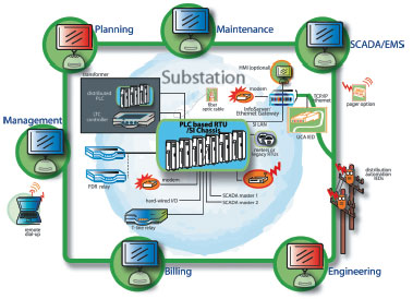
The newer, processor based, IED devices provide exponentially more data/information than the previous generation of equipment. Substation automation systems play a critical role for utilities by leveraging IEDs for capturing real-time and time stamped historical information, providing a foundation layer for delivering the critical data to the utility knowledge infrastructure (see Enterprise-Wide Data Sharing graphic).This enhanced availability of station data enables utilities to make business and operating decisions more accurately and quickly, and to improve the quality of service provided to customers, while maintaining acceptable levels of risk and reliability.
Due to the likelihood that substation data is going to all feed into a small number of central databases, depending on the external repository architecture, the information from each substation has to be consistent in format and scope. The means of gathering and storing this data in the substation must therefore also be consistent to ensure that the same communications interface can be used between substation and external databases.
Configuration of IEDs
Modern IEDs are capable of providing a vast amount of information to the local HMI and remote SCADA interfaces. Before a standard configuration plan can be formed for each IED, the enterprise wide data requirements of the utility need to be determined. Examples of the major areas of the enterprise that use data include real-time fault dispatch, load management, reliability maintenance, asset planning and revenue management.
Once enterprise data requirements are defined, configuration decisions such as variable assignment and hardwired input utilization can be determined, based on the capability of the IED, redundancy standards and data quality requirements. Spare capacity for future additions should be part of every configuration.
Many modern IEDs are capable of supporting millisecond time stamped hardwired inputs which can replace data concentration devices. This could be used as a primary means of concentrating hardwired inputs, or in conjunction with other data concentration devices, or not at all, depending on the design principles which include scalability planning. The device used to concentrate hardwired inputs should also include spare capacity. Whatever the design principles may be, the same relay configuration should be used for a specific IED and its assigned protective function. In other words, a certain model IED used to protect a bank will employ one standard if all banks can be considered the same. This is unlikely however, so new standards based on a variation of the core bank model would be needed, such as the inclusion of load tap changers.
Presentation of information at the substation interface
Modern HMI software should support alarm configuration to allow the substation user to prioritize alarms, define their behavior, define analog limits, standardize nomenclature and graphical image, to name a few items that contribute to the operability and presentation of HMI information. Users at the substation should be able to walk into every different substation and find a standard configuration applied to every component in that substation. Of course, differences will exist in areas such as bus architecture, so allowances in the data model should also be made, to a reasonable extent, for typical architecture categories.
Presentation of information to SCADA
The level of real-time detail available at the local substation interface is more than what is required for communication to SCADA. Certain types of points may simply be grouped together into logic points so that only one alarm is presented to SCADA in the event that one alarm in a group becomes active. Other points may not need to go to SCADA at all; others may need to be sent with the addition of a timestamp. These decisions should be made with the function of the SCADA dispatcher in mind – what level of information is needed so that the dispatcher can assign the correct crew with enough information for them to be properly prepared, whatever problem the substation is experiencing. The principles of communicating with SCADA should be standardized across all installations.
Automation within the substation
PLC or other logic based controllers allow the ability to automatically switch within a substation in response to pre-defined events or triggers. Logic “building blocks” should comprise clear rules that are low level enough to be assembled around the various designs present in the utility’s substations.
Communication protocols employed
Due to the availability of multiple communication ports on substation devices, redundant communications is feasible and provides increased reliability and separation of relay communication features. One port can be used primarily for data transfer while the other ports can be used for relay maintenance (loopthru), failover, fault record transfer, mirrored bit or other functions that are important but whose separation from real-time data flow may increase the efficiency of this primary data flow function. Certain protocols will not support a full range of potential SCADA data, such as pulse accumulation, so obviously the device model used should include protocols that fully support the data, or appropriate protocol conversion will be needed.
Employing diversity of communication protocols among ports, and diversity of data concentration devices connected to these ports, will guard against common mode failure. Communication redundancy also extends beyond the substation, up to the SCADA Master. The advantage of communication redundancy is not only the failover ability but also the minimized duration of SCADA outage during maintenance on either communications path, at any point along the path inside or outside of the substation. This certainly helps the time pressure associated with continuing automation enhancements once communication is established, as it allows more flexible upgrade scheduling when communication down-time is minimized.
Protective circuit design
Wiring standards for the integration of an IED and it’s connected components (such as blocking switches, terminal blocks, current transformers, etc.), specific to the protective application, are established to allow for consistent design and construction practice. Consistent design leads to consistent construction practice. Installation errors due to inconsistent design can result in significant setbacks during cutover, potentially leading to damage or unplanned outages.
Plan for Change
Large scale implementations last multiple years, leading to complicating factors such as hardware obsolescence, firmware upgrades, software upgrades and protocol improvements during the course of deployment. No matter how much effort is put into defining requirements and staying focused on scope, change is inevitable. Fortunately, change can be beneficial if managed correctly.
Effective communications is key to managing change. Before any automation or upgrade work proceeds, a change control board should be formed with at least one member from each group of stakeholders that was involved in the formation of requirements for the project. The end result for most changes is a revision to one or more templates or design standards – essentially an update of the data model. Decisions regarding the implementation of changes across a large number of substations in varying stages of design or installation have far reaching ramifications. Separate change/retrofit plans are required depending on this status and the nature of the change.
As mentioned previously, planning at the IED configuration and data concentration level should include spare capacity for future additions. Adding a few hardwired points will not require much in the way of process to manage. Adding IED points may require more however. This is one of many drivers for change in substation automation.
Changes to plan for include configuration changes and component changes.An effective rollout procedure expedites change implementation.
Configuration changes
An example of a configuration change would be a change to the IED point configuration. For substations already upgraded, a retrofit plan will be needed to ensure minimal interruption to the service of each substation. The same retrofit plan could be applied to substations undergoing an upgrade, but without the same restrictions on limiting down time. Substations undergoing factory testing should be completed to the current configuration and then undergo the change with regression testing applied to any part of the system that is affected by the change. For substations in the design or build phase, the configuration change should be made before testing starts.
Component changes
An example of a component change would be an upgrade to a software module, or a hardware component. This type of change should be made in the factory first, to ensure that the change is robust and results in the desired outcome. The change should be made on a system about to undergo testing, so that a full factory test can be made with the change in place to better ensure its quality. Regressive testing should also take place which will be described in the next section. The factory environment cannot fully simulate the real world utility environment so the next step in approving the change would be to implement the change on a test system integrated to the SCADA network and as many typical substation components as possible.
Rollout procedure
Efficient implementation of a change requires the ability to remotely access the substation automation system, to reduce “windshield” time and ensure quick rollout across the substation network. Many substation components, such as GPS time clocks, now provide a communications port for maintenance purposes. If the automation system includes a PC or other device capable of connection to these maintenance ports, the scope of remote maintenance is increased beyond simply the configuration of the HMI and SCADA interface. Redundant communications to the station and IEDs will also allow remote maintenance of IED settings with little or no risk of impact on primary data communications.
Factory Testing
The fastest way to test a system is to make sure that it is as close to error free as possible, before you test! System build and configuration procedures must be well documented, comprehensive and repeatable for this to be achievable. Attention to this detail will result in a quality product for site installation and acceptance testing. The physical hardware assembly must match the design of course so a system inspection is necessary upon receipt of the build. This step will save time over troubleshooting hardware issues whose symptoms may be the result of many possible problems.
Once inspection is confirmed, configuration will take place according to procedures that are documented and physically signed off after each step. This creates a factory configuration history that can be verified before testing begins. Similar documentation should be utilized for the actual testing, so that sign-off of all steps can be verified before site installation.
Factory test procedures should be designed to test the complete configuration of the integrated system, rather than the complete functionality of all system components. Each system component should go through complete functionality testing once, but is not needed on an installation basis. If a system component is upgraded, regressive testing on this single component should be performed one time to verify the complete functionality is still intact.
Efficiency of Installation
Site installation relies on comprehensive work construction plans and consideration of existing substation conditions for ease of cutover. An initial site meeting should take into consideration the components to be removed or replaced and the best design standard to apply. Replacement of relay panels will be much simpler if the existing supporting structure can be re-used for the new panels. The structure of the panel design could be modified as a variation to allow for a more “plug-and-play” approach, while the wiring standard for the panel remains the same.
Site acceptance testing requires coordination between many different people so the procedures for this testing will require similar quality assurance to that used in factory testing. Site acceptance testing includes an important additional component; authority for conducting each step of the test procedure must be well established because of the risks associated with working in a substation environment versus a factory environment.
Additional techniques can be used to improve the efficiency of installation, once the reliability is established through procedure and authority. One such technique is the use of “dummy” IEDs to conduct testing without directly affecting critical substation components. This can establish a correct configuration so that the actual test involving the critical component can be carried out with a higher level of confidence. Due to the paramount importance of the protective responsibilities of IEDs in a substation, another technique would be to provide a single point of access for technicians responsible for IED maintenance. Instead of requiring a relay technician to directly connect to the maintenance port of an IED during site acceptance, to support ongoing testing, communications from each IED can be feed back to a central location in the substation near to the local interface. This allows the relay technician to easily communicate to all IEDs within a substation from one point and be more closely involved with the other members of the testing team. This local interface will need to provide some sort of blocking mechanism to the remote loopthru interface to prevent conflicts.
Scheduling
Scheduling is critical to the implementation of large scale automation projects. There are many teams involved in the overall work flow so the project processes to achieve each milestone in commissioning a system should be documented. These processes would include roles and responsibilities of every team member, deliverables required at each stage of the process and clear timelines to ensure that parallel processes are synchronized.
If the site installation process falls behind, systems waiting to be installed will build up which complicates retrofit plans for approved changes. If design or factory testing falls behind, construction teams could be left with no work which could result in their re-assignment to work outside of the substation automation upgrade project. Delays will likely occur at every stage in the project process so the scheduling should include some buffering to mitigate this risk.
If the throughput of each stage in the project is sized and matched to the other stages, the workflow from design through to commissioning can be leveled.
A seasoned systems integrator can provide discipline and experience for large scale automation projects. Internal utility teams that are fully capable of dealing with single implementation type projects may not be prepared to handle multiple projects. A systems integrator brings tailored best practices to help the utility achieve maximum value from their substation automation investments, and to reduce risk of applicability, implementation and acceptance.
About the Author
Lee Melville is a project engineer with Enspiria Solutions, Inc. He has 10 years of experience in the electrical utility industry, and specializes in the integration of substation automation systems. Lee holds a B.E. in Electrical Engineering with honors and an M.E. in Engineering Management from the University of Canterbury (Christchurch, New Zealand). His experience includes positions with UnitedNetworks Ltd., Power New Zealand, and Tait Electronics.lmelville@enspiria.com
There are many substation automation architecture choices available today providing varying levels of redundancy and scalability, but the application of standards and process to implementation of the selected architecture is critical. Successful large scale substation automation must start with data and integration standards, and include planning for change.Comprehensive factory testing, efficient installation techniques, and effective scheduling are also critical to the implementation of large scale projects.
Start with Data and Integration Standards
With the wealth of information available from IEDs and other devices currently being installed in substations, data serves the needs of many people. In fact, with regards to the diversity of stakeholders associated with a project, substation automation is one of the most complex undertakings a utility can perform. Defining the integration of these devices demands the involvement of all stakeholders to register their requirements.
Structured data modeling is necessary not only for each type of device that will be integrated into the substation automation system but also for the functional configuration of that device. For example, a protective overcurrent relay could be used to protect feeder level circuits or subtransmission level circuits – these two functions should be defined in separate data models.
Structured data modeling ensures a base standard from which to drive the combination of substation components into an integrated system. Communication protocols such as IEC 61850 provide comprehensive data modeling for the information out of devices that utilize this protocol, but the complete substation automation upgrade goes beyond this.
The data modeling exercise should incorporate the following factors:
- Presentation of information to the Enterprise
- Configuration of IEDs
- Presentation of information at the substation interface
- Presentation of information to SCADA
- Automation within the substation
- Communication protocols employed
- Protective circuit design
All of these factors should make up the data model which is utilized to create the various configuration builds for any particular substation architecture. Each of these categories should be well documented in templates or design standards which are well understood and agreed upon before they are put into practice.
Presentation of information to the enterprise
The newer, processor based, IED devices provide exponentially more data/information than the previous generation of equipment. Substation automation systems play a critical role for utilities by leveraging IEDs for capturing real-time and time stamped historical information, providing a foundation layer for delivering the critical data to the utility knowledge infrastructure (see Enterprise-Wide Data Sharing graphic).This enhanced availability of station data enables utilities to make business and operating decisions more accurately and quickly, and to improve the quality of service provided to customers, while maintaining acceptable levels of risk and reliability.
Due to the likelihood that substation data is going to all feed into a small number of central databases, depending on the external repository architecture, the information from each substation has to be consistent in format and scope. The means of gathering and storing this data in the substation must therefore also be consistent to ensure that the same communications interface can be used between substation and external databases.
Configuration of IEDs
Modern IEDs are capable of providing a vast amount of information to the local HMI and remote SCADA interfaces. Before a standard configuration plan can be formed for each IED, the enterprise wide data requirements of the utility need to be determined. Examples of the major areas of the enterprise that use data include real-time fault dispatch, load management, reliability maintenance, asset planning and revenue management.
Once enterprise data requirements are defined, configuration decisions such as variable assignment and hardwired input utilization can be determined, based on the capability of the IED, redundancy standards and data quality requirements. Spare capacity for future additions should be part of every configuration.
Many modern IEDs are capable of supporting millisecond time stamped hardwired inputs which can replace data concentration devices. This could be used as a primary means of concentrating hardwired inputs, or in conjunction with other data concentration devices, or not at all, depending on the design principles which include scalability planning. The device used to concentrate hardwired inputs should also include spare capacity. Whatever the design principles may be, the same relay configuration should be used for a specific IED and its assigned protective function. In other words, a certain model IED used to protect a bank will employ one standard if all banks can be considered the same. This is unlikely however, so new standards based on a variation of the core bank model would be needed, such as the inclusion of load tap changers.
Presentation of information at the substation interface
Modern HMI software should support alarm configuration to allow the substation user to prioritize alarms, define their behavior, define analog limits, standardize nomenclature and graphical image, to name a few items that contribute to the operability and presentation of HMI information. Users at the substation should be able to walk into every different substation and find a standard configuration applied to every component in that substation. Of course, differences will exist in areas such as bus architecture, so allowances in the data model should also be made, to a reasonable extent, for typical architecture categories.
Presentation of information to SCADA
The level of real-time detail available at the local substation interface is more than what is required for communication to SCADA. Certain types of points may simply be grouped together into logic points so that only one alarm is presented to SCADA in the event that one alarm in a group becomes active. Other points may not need to go to SCADA at all; others may need to be sent with the addition of a timestamp. These decisions should be made with the function of the SCADA dispatcher in mind – what level of information is needed so that the dispatcher can assign the correct crew with enough information for them to be properly prepared, whatever problem the substation is experiencing. The principles of communicating with SCADA should be standardized across all installations.
Automation within the substation
PLC or other logic based controllers allow the ability to automatically switch within a substation in response to pre-defined events or triggers. Logic “building blocks” should comprise clear rules that are low level enough to be assembled around the various designs present in the utility’s substations.
Communication protocols employed
Due to the availability of multiple communication ports on substation devices, redundant communications is feasible and provides increased reliability and separation of relay communication features. One port can be used primarily for data transfer while the other ports can be used for relay maintenance (loopthru), failover, fault record transfer, mirrored bit or other functions that are important but whose separation from real-time data flow may increase the efficiency of this primary data flow function. Certain protocols will not support a full range of potential SCADA data, such as pulse accumulation, so obviously the device model used should include protocols that fully support the data, or appropriate protocol conversion will be needed.
Employing diversity of communication protocols among ports, and diversity of data concentration devices connected to these ports, will guard against common mode failure. Communication redundancy also extends beyond the substation, up to the SCADA Master. The advantage of communication redundancy is not only the failover ability but also the minimized duration of SCADA outage during maintenance on either communications path, at any point along the path inside or outside of the substation. This certainly helps the time pressure associated with continuing automation enhancements once communication is established, as it allows more flexible upgrade scheduling when communication down-time is minimized.
Protective circuit design
Wiring standards for the integration of an IED and it’s connected components (such as blocking switches, terminal blocks, current transformers, etc.), specific to the protective application, are established to allow for consistent design and construction practice. Consistent design leads to consistent construction practice. Installation errors due to inconsistent design can result in significant setbacks during cutover, potentially leading to damage or unplanned outages.
Plan for Change
Large scale implementations last multiple years, leading to complicating factors such as hardware obsolescence, firmware upgrades, software upgrades and protocol improvements during the course of deployment. No matter how much effort is put into defining requirements and staying focused on scope, change is inevitable. Fortunately, change can be beneficial if managed correctly.
Effective communications is key to managing change. Before any automation or upgrade work proceeds, a change control board should be formed with at least one member from each group of stakeholders that was involved in the formation of requirements for the project. The end result for most changes is a revision to one or more templates or design standards – essentially an update of the data model. Decisions regarding the implementation of changes across a large number of substations in varying stages of design or installation have far reaching ramifications. Separate change/retrofit plans are required depending on this status and the nature of the change.
As mentioned previously, planning at the IED configuration and data concentration level should include spare capacity for future additions. Adding a few hardwired points will not require much in the way of process to manage. Adding IED points may require more however. This is one of many drivers for change in substation automation.
Changes to plan for include configuration changes and component changes.An effective rollout procedure expedites change implementation.
Configuration changes
An example of a configuration change would be a change to the IED point configuration. For substations already upgraded, a retrofit plan will be needed to ensure minimal interruption to the service of each substation. The same retrofit plan could be applied to substations undergoing an upgrade, but without the same restrictions on limiting down time. Substations undergoing factory testing should be completed to the current configuration and then undergo the change with regression testing applied to any part of the system that is affected by the change. For substations in the design or build phase, the configuration change should be made before testing starts.
Component changes
An example of a component change would be an upgrade to a software module, or a hardware component. This type of change should be made in the factory first, to ensure that the change is robust and results in the desired outcome. The change should be made on a system about to undergo testing, so that a full factory test can be made with the change in place to better ensure its quality. Regressive testing should also take place which will be described in the next section. The factory environment cannot fully simulate the real world utility environment so the next step in approving the change would be to implement the change on a test system integrated to the SCADA network and as many typical substation components as possible.
Rollout procedure
Efficient implementation of a change requires the ability to remotely access the substation automation system, to reduce “windshield” time and ensure quick rollout across the substation network. Many substation components, such as GPS time clocks, now provide a communications port for maintenance purposes. If the automation system includes a PC or other device capable of connection to these maintenance ports, the scope of remote maintenance is increased beyond simply the configuration of the HMI and SCADA interface. Redundant communications to the station and IEDs will also allow remote maintenance of IED settings with little or no risk of impact on primary data communications.
Factory Testing
The fastest way to test a system is to make sure that it is as close to error free as possible, before you test! System build and configuration procedures must be well documented, comprehensive and repeatable for this to be achievable. Attention to this detail will result in a quality product for site installation and acceptance testing. The physical hardware assembly must match the design of course so a system inspection is necessary upon receipt of the build. This step will save time over troubleshooting hardware issues whose symptoms may be the result of many possible problems.
Once inspection is confirmed, configuration will take place according to procedures that are documented and physically signed off after each step. This creates a factory configuration history that can be verified before testing begins. Similar documentation should be utilized for the actual testing, so that sign-off of all steps can be verified before site installation.
Factory test procedures should be designed to test the complete configuration of the integrated system, rather than the complete functionality of all system components. Each system component should go through complete functionality testing once, but is not needed on an installation basis. If a system component is upgraded, regressive testing on this single component should be performed one time to verify the complete functionality is still intact.
Efficiency of Installation
Site installation relies on comprehensive work construction plans and consideration of existing substation conditions for ease of cutover. An initial site meeting should take into consideration the components to be removed or replaced and the best design standard to apply. Replacement of relay panels will be much simpler if the existing supporting structure can be re-used for the new panels. The structure of the panel design could be modified as a variation to allow for a more “plug-and-play” approach, while the wiring standard for the panel remains the same.
Site acceptance testing requires coordination between many different people so the procedures for this testing will require similar quality assurance to that used in factory testing. Site acceptance testing includes an important additional component; authority for conducting each step of the test procedure must be well established because of the risks associated with working in a substation environment versus a factory environment.
Additional techniques can be used to improve the efficiency of installation, once the reliability is established through procedure and authority. One such technique is the use of “dummy” IEDs to conduct testing without directly affecting critical substation components. This can establish a correct configuration so that the actual test involving the critical component can be carried out with a higher level of confidence. Due to the paramount importance of the protective responsibilities of IEDs in a substation, another technique would be to provide a single point of access for technicians responsible for IED maintenance. Instead of requiring a relay technician to directly connect to the maintenance port of an IED during site acceptance, to support ongoing testing, communications from each IED can be feed back to a central location in the substation near to the local interface. This allows the relay technician to easily communicate to all IEDs within a substation from one point and be more closely involved with the other members of the testing team. This local interface will need to provide some sort of blocking mechanism to the remote loopthru interface to prevent conflicts.
Scheduling
Scheduling is critical to the implementation of large scale automation projects. There are many teams involved in the overall work flow so the project processes to achieve each milestone in commissioning a system should be documented. These processes would include roles and responsibilities of every team member, deliverables required at each stage of the process and clear timelines to ensure that parallel processes are synchronized.
If the site installation process falls behind, systems waiting to be installed will build up which complicates retrofit plans for approved changes. If design or factory testing falls behind, construction teams could be left with no work which could result in their re-assignment to work outside of the substation automation upgrade project. Delays will likely occur at every stage in the project process so the scheduling should include some buffering to mitigate this risk.
If the throughput of each stage in the project is sized and matched to the other stages, the workflow from design through to commissioning can be leveled.
A seasoned systems integrator can provide discipline and experience for large scale automation projects. Internal utility teams that are fully capable of dealing with single implementation type projects may not be prepared to handle multiple projects. A systems integrator brings tailored best practices to help the utility achieve maximum value from their substation automation investments, and to reduce risk of applicability, implementation and acceptance.
About the Author
Lee Melville is a project engineer with Enspiria Solutions, Inc. He has 10 years of experience in the electrical utility industry, and specializes in the integration of substation automation systems. Lee holds a B.E. in Electrical Engineering with honors and an M.E. in Engineering Management from the University of Canterbury (Christchurch, New Zealand). His experience includes positions with UnitedNetworks Ltd., Power New Zealand, and Tait Electronics.lmelville@enspiria.com