 Abstract
The calculation of the short circuit capacity for the conductors and screens of power cables is based upon the popular adiabatic method. Disregarding heat transfer occurrence results in a conservative calculation, mainly for small sections such as those of the screen wires. To obtain a more realistic approximation we could virtually increase the maximum temperature used for the adiabatic calculation. In this paper we give an indication about such temperature increase both for conductors and metallic screens.
Introduction
Sophisticated software computations are available for the calculation of short-circuit ratings of both the conductor and metallic screen of virtually any power cable. However the basis for most of the short-circuit calculations is the international standard IEC 949. The method proposed by this standard takes into account the heat transfer through the adjacent materials of both conductor and metallic screen during a short-circuit situation– non-adiabatic heating.
Traditionally the short-circuit ratings are calculated on an adiabatic basis, assuming that all the heat generated is retained inside the metallic parts of the cable. This assumption provides a safety margin relatively to the non-adiabatic method.
Assuming an adiabatic process, all the heat generated by Joule effect in the metallic components of the cable determines that the maximum transient temperature is obtained through the following expression:
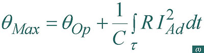
Figure 1. Virtually imposed temperature increase for an aluminium conductor.
being qOp the continuous operation temperature, C the heat capacity of the conductor and R its electrical resistance. The fault current IAd is provided for a transient time period t.
The maximum allowed temperature is specified in order to avoid severe thermal stresses leading an accelerated ageing of the individual components of the cable. In the case of two of the most popular insulation materials: cross linked polyethylene (XLPE) and synthetic rubber (Ethylene Propylene Rubber, EPR), the maximum transient permissible temperature is 250 ºC.
In order to account for heat transfer in the fault ratings for the conductors and metallic screens, the IEC 949 standard introduces an empirical factor e, so that the relationship between the fault ratings obtained by the adiabatic (IAd) and non-adiabatic (InAd) methods is:
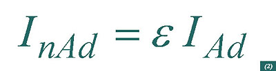
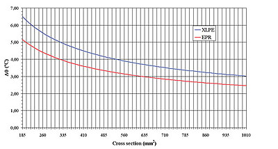
Figure 2. Virtually imposed temperature increase for a copper conductor.
The factor e is specified for each of the metallic parts of the power cable, but in this work we will only concentrate on the conductor and metallic screen.
Conductor
Since the adiabatic rating is always more conservative than its non-adiabatic counterpart, we can assume in the first method a maximum temperature superior to recommended values determined by the insulation material, in order to obtain a short-circuit current identical to the one obtained by the non-adiabatic method. This would be of course a virtual increase in the maximum temperature, serving only for calculation purposes.
Therefore for aluminium conductors the virtual increase in the maximum temperature will be:
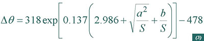
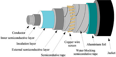
Figure 3. A 60kV XLPE cable with a copper wire screen.
Where:
S: conductor cross-section;
a=1.702 mm; b=0.477 mm2 for a XLPE insulation;
a=1.314 mm; b=0.298 mm2 for a EPR insulation (>3 kV).
The value of such increase of temperature is depicted in Figure 1 as a function of the cross section of the aluminium conductor.
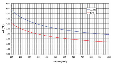
Figure 4. Virtually imposed temperature increase for a copper screen.
For a copper conductor the virtual increase of the maximum temperature would be:
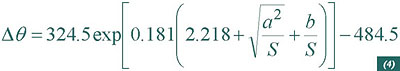
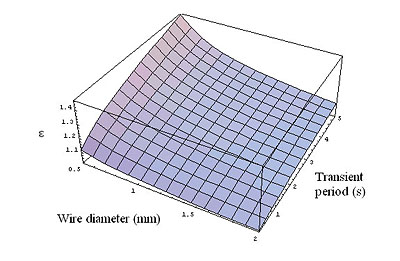
Figure 5. The ratio e introduced by expression 2 as a function of the screen wire diameter and transient period.
Where:
S: conductor cross-section;
a=0.909 mm; b=0.226 mm2 for a XLPE insulation;
a=0.710 mm; b=0.155 mm2 for a EPR insulation (>3 kV).
Figure 2 shows the behaviour of the virtual temperature increase as a function of the copper conductor cross-section.
The fault current is now calculated through what we could call a modified adiabatic method:
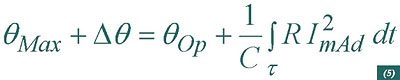
For both aluminium and copper conductors, the fault current rating obtained through the previous expression (ImAd) is identical to its non-adiabatic counterpart (InAd) calculated according to the standard IEC 949. Assuming a transient of 1 second and a XLPE insulation, the maximum deviation for the conductor cross section range of Figures 1 and 2, is 2.14% for an aluminium conductor with a cross section of 185 mm2, and 1.62% for a copper conductor with the same cross section.
Metallic screen
This metallic layer is applied over the semiconductive insulation screen, and acts in normal operation conditions as a return path for both capacitive charging currents and induced currents. In the event of an electrical fault such metallic screen can also carry short circuit currents. For illustration purposes we will consider a metallic screen made up of copper wires helically stranded over a XLPE semiconductive insulation layer. In order to avoid screen wire impressions due to heating, the copper wires are applied over screen bedding in the form of a semiconductive tape (Figure 3). To reinforce the moisture barrier and to ensure proper bedding, a semiconductive water blocking tape is applied over the copper wires.
By using the same method applied to the conductors, we can obtain the maximum virtual temperature that could be introduced into the adiabatic computations in order to take into account the heat transfer that occurs in reality. The expression obtained this way is far more tedious than the ones obtained for the conductors – expressions 4 and 5. Therefore we will only show the respective behaviour as a function of the diameter of the copper wires used in the metallic screen (Figure 4).
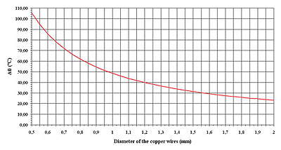
For a specific wire diameter we can calculate the non-adiabatic short-circuit current by using the above data on expression 5. The ratio factor e depicted in Figure 5 as a function of the wire diameter and short-circuit transient period, indicates a significant increase of the short-circuit current obtained by taking into account the heat transfers when compared with the adiabatic method. This is particularly notorious for the smallest wire diameters. If we consider a transient period of 1 second, the effective short-circuit current of a screen composed with copper wires with a diameter of 0.5 mm shows an increase of near 22% when compared with the value obtained by the adiabatic method. For a 2 mm wire the gap is reduced to 6%.
Conclusions
Following the principles announced on the international standard IEC 949, we propose a simplistic approach based on a virtual increase of the maximum transient temperature used in the traditional and more conservative adiabatic method. Such increase in the maximum temperature was defined by taking into account the heat transfers that occur in reality. This way the design engineer can obtain more reliable result out of the traditional adiabatic method, especially for the metallic components of the power cable with reduced cross section (namely the screen).
Biography
Pedro Cavaleiro, received both his BSc degree in Physics and his MSc in Electrical Engineering from the Porto University (Portugal). He spent 6 years in a R&D institute, devoting most of his efforts in the field of electric current sensors for high voltage overhead lines. In 1999 he joined the Portuguese cable manufacturing group Quintas & Quintas, and he is currently co-responsible for the Engineering Department, where his experience is focused in the areas of product design, application and installation. He is author and co-author of several papers on electrical current sensors and cable design.
References
1. IEC standard 949, “Calculation of thermally permissible short-circuit currents, taking into account non-adiabatic heating effects”.