Introduction
Ethernet local area networks (LANs) are steadily gaining more acceptance in substation automation applications where the LAN has become an integral part of the protection and control system. Most protective relaying manufacturers now offer Ethernet ports on their relays in both fiber optical and copper media. Information models and exchange methods currently being defined as part of the IEC 61850 standard allow for real-time control (e.g. Trip/Block) messages to be sent across the LAN between relays or other intelligent electronic devices (IEDs). Furthermore there is a trend towards multicasting sampled data of current and voltage parameters over a 100Mbps Ethernet LAN as defined in IEC 61850-9-2 (Process Bus). With Ethernet LANs playing such a critical role in protection and control systems new standards such as IEEE 802.1W Rapid Spanning Tree Protocol which are used to implement network redundancy and ring architectures are of critical importance.
Background
Ethernet switches operate by forwarding traffic between their ports. The switch examines each Ethernet frame and records (learns) its MAC address and the port upon which it resides. When a frame arrives for a given MAC address, the switch "knows" on which outgoing port to send it. If a frame arrives and its destination MAC address is unknown, the switch will “flood” the frame out all of its ports.
If switches in the network are connected in a loop a ‘broadcast storm’ will result where a single broadcast frame will circulate endlessly. This condition consumes all available bandwidth on the loop making the network unusable. The Spanning Tree Protocol is used to prevent this situation.
Brief history of Spanning Tree Protocol (STP) and Rapid STP (RSTP)
The Spanning Tree Protocol (IEEE 802.1D) was designed to solve the fundamental problem of traffic loops. The key idea in STP is to prune (looping) links in order to reduce the network topology to that of a tree. The resulting tree “spans” (i.e. connects) all switches, but eliminates loops. The steps in order to best accomplish this process are:
The STP protocol has proved to be the tried and tested method for providing path redundancy while eliminating loops. The STP protocol does suffer from a number of drawbacks that limit its applicability, namely:
Enter RSTP (IEEE 802.1w)
RSTP solves STP's problem with failover time by a number of means. Whereas STP switches store only the best path to the root switch, RSTP switches store all potential paths. When links fail, RSTP has pre-calculated routes to fall back upon. Additionally, unlike STP switches, an RSTP switch will respond to another switch that advertises an inferior or incorrect route to the root switch. This information allows the switch with incorrect information to be rapidly trained.
RSTP solves STP's problem with lengthy recovery time by introducing a new procedure called proposing-agreeing. Proposing and agreeing works after a better path to the root is restored by “shuffling” the restored part of the network one hop at a time towards the network edge. This method also enables the network to come up quickly at inception.
RSTP also introduces a method for quickly bringing up ports at the edge of the network, while still protecting them against loops. If the port is designated as an “edge” type of port, RSTP will continue to send configuration messages out the port (in order to detect loops) but will allow traffic to flow as soon as the port rises. In the event of a loop, some looped traffic may flow before RSTP quickly seals the network. PC’s, IEDs and RTUs connected via edge ports can send traffic without the extensive delays imposed by RSTP.
Rings
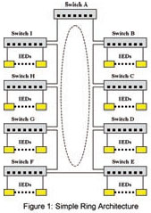
A ring topology offers built-in redundancy and is often the most economical in terms of interconnection costs. Two popular methods of implementing rings are collapsed backbone and
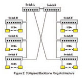
distributed switch. The distributed switch method, or simple ring (See Figure 1), is employed when network connected IEDs are geographically distributed. The IEDs at each location are aggregated onto switches, which are organized into a ring. The connections between switches in the ring may be made using dual redundant links to obviate the possibility of failure at a fiber, connector or port level. The collapsed backbone method (See Figure 2) is usually employed when a large number of network connected IEDs are located in close proximity to one another. The IEDs are aggregated onto switches, the switches organized into a number of rings and all rings terminated in a common root node. Quite often the network topology is a mixture of both methods, such as a ring of rings. Traffic in a ring tends to be balanced. The ring
will open itself with an equal number of switches on either side of the root switch given an odd number of switches in the ring.
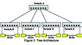
Latency in ring networks tends to be greater than in tree networks (See Figure 3) as there are usually more hops to pass through in order to go anywhere useful. The worst case occurs when switches on either end of the blocked link at the “bottom” of the ring need to forward to each other. In this case traffic must flow through every switch in the ring.
Ring networks offer only slightly slower failover and recovery times than tree networks. The worst case link failure in ring networks occurs on a port at the root. In this failure case half of the switches in the ring must retrain themselves to face their root port in a completely opposite direction after a link failure or recovery. The other half of the network must reverse the direction of transmission to switches in the failing half.
The size of the ring is in theory limited by the RSTP switch diameter, which assumes a pessimistic transit delay of one second per switch. In practice the maximum number of switches in an optimized ring occurs when the number of priority switch levels has been exhausted. This limits the size of the ring to 31 switches. Rings of more than 31 switches are still possible but will failover and recover in a slower fashion.
Failover Performance In Rings
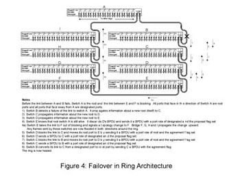
Figure 4 presents a network of nine switches organized in a ring topology. The figure details the sequence of steps to heal the ring after the link between switches A and B fails.
Initially, switch B has information only about root switch A. All information about the root switch flows towards the break between switch E and F. After link AB fails switch B recognizes the failure and must concludes that it is the root switch, propagating the information towards C.
The information will continue to propagate around the ring until it reaches the portion of the network that is still aware a path to switch A exists (i.e. switch E).
Switch E propagates correct information towards switches D, C and B. Since these switches are changing the identity of their root ports, they must use the proposal-agreement process to achieve rapid forwarding.
Typically, each step in the process involves a protocol “think time” and a frame transmission time, the sum of which is less than about 3 milliseconds. This leads to a total failover time for the ring of about 27 milliseconds. There is also the time required to signal topology change to switches F-A. In this example the topology change time is interleaved with the failover process and does not contribute to the failover time.
The recovery process for this example is quite straightforward. When link AB is restored, switch A will transmit a BPDU down it. Switch B will change its root port towards A, and then signal a topology change. Switch B will propagate the new root information towards switch C. Switch C will change its root port and will train switch D. Switch D will train switch E. Switch E will attempt to train switch F but switch F will see a lower path cost from switch G and will discard the BPDU from E. At this point the network will be healed.
When switch A receives the topology change from B it propagates the topology change towards switches I-F. During the recovery process switch A will continue to forward a number of frames for switches B-E in the direction of switch I. At some point these frames will encounter a newly blocked link on switch C-E. Fortunately, switch A will use the topology change to start flooding frames, as will switches I through F. Switch A will lose about 2 milliseconds worth of frames, switch I 4 milliseconds, switch H 6 milliseconds, switch G 8 milliseconds and switch F 10 milliseconds worth of frames.
NOTE:
The performance levels were achieved using RuggedCom’s RuggedSwitch™ family of managed switches employing RuggedCom’s implementation of the IEEE 802.1W RSTP standard. Enhancements were made in the implementation to optimize performance for ring architectures while maintaining interoperability with other vendors.
Dual Link arrangement
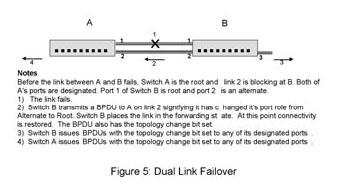
Figure 5 presents two switches protected by a dual link arrangement, and the series of events that occur after a link failure.
Both switch’s detect failure of link 1 simultaneously and immediately age out the learned MAC address entries for these ports.
Switch B has been receiving periodic transmissions of Bridge Protocol Data Units (BPDUs)1 on link 2. This information allows it to evaluate link 2 as its best path to the to the root switch. Switch B immediately sets its root port to 2.
RSTP procedure requires a topology change when adding a path to the topology. Switch B “sees” the new root port as an added path and floods topology changes out its ports. Though not strictly necessary in this case, they cause no ill effects.
Including the time to recognize the link failure (an process that takes less than a millisecond) the switches failover to link 2 in less than 5 milliseconds.
The recovery process for this example is quite straightforward. When link 1 is restored, switch’s A and B will transmit BPDUs on it. Switch A will ignore the BPDU from switch B. Switch B will use the switch A BPDU to place its link 2 in blocking and then change its root port towards A. Afterwards, switch B will signal a topology change to switch A. At this point the network will be healed. The recovery process introduces an outage of less than 5 milliseconds.
NOTES:
1 – BPDU (Bridge Protocol Data Units) messages are used by managed Ethernet Switches on the network as defined in the IEEE 802.1W Rapid Spanning Tree protocol.
Conclusions
About the Authors:
Michael Galea is a senior software developer at RuggedCom Inc. which designs and manufactures industrially hardened networking and communications equipment for harsh environments. Prior to joining RuggedCom Mr. Galea was involved in the development of Frame Relay/X.25 Switches and IP/IPX Routing/Bridging technology. Mr. Galea graduated from the University of Toronto, Toronto, Ontario in 1983 with a Bachelor of Applied Science degree.
Marzio Pozzuoli is the founder and president of RuggedCom Inc. which designs and manufactures industrially hardened networking and communications equipment for harsh environments. Prior to founding RuggedCom Mr. Pozzuoli developed advanced numerical protective relaying systems and substation automation technology. Mr. Pozzuoli graduated from Ryerson Polytechnical Institute, Toronto, Ontario in 1986 with a Bachelor of Electrical Engineering Technology. He holds multiple patents related to advances in communications, protective relaying technology, and automation technology. He is also an active member of the IEEE and is involved standards work as a member of the IEEE Power Engineering Society Substations Committee task force C2TF1 working on developing a standard for communications networking devices in substations.
References:
Ethernet local area networks (LANs) are steadily gaining more acceptance in substation automation applications where the LAN has become an integral part of the protection and control system. Most protective relaying manufacturers now offer Ethernet ports on their relays in both fiber optical and copper media. Information models and exchange methods currently being defined as part of the IEC 61850 standard allow for real-time control (e.g. Trip/Block) messages to be sent across the LAN between relays or other intelligent electronic devices (IEDs). Furthermore there is a trend towards multicasting sampled data of current and voltage parameters over a 100Mbps Ethernet LAN as defined in IEC 61850-9-2 (Process Bus). With Ethernet LANs playing such a critical role in protection and control systems new standards such as IEEE 802.1W Rapid Spanning Tree Protocol which are used to implement network redundancy and ring architectures are of critical importance.
Background
Ethernet switches operate by forwarding traffic between their ports. The switch examines each Ethernet frame and records (learns) its MAC address and the port upon which it resides. When a frame arrives for a given MAC address, the switch "knows" on which outgoing port to send it. If a frame arrives and its destination MAC address is unknown, the switch will “flood” the frame out all of its ports.
If switches in the network are connected in a loop a ‘broadcast storm’ will result where a single broadcast frame will circulate endlessly. This condition consumes all available bandwidth on the loop making the network unusable. The Spanning Tree Protocol is used to prevent this situation.
Brief history of Spanning Tree Protocol (STP) and Rapid STP (RSTP)
The Spanning Tree Protocol (IEEE 802.1D) was designed to solve the fundamental problem of traffic loops. The key idea in STP is to prune (looping) links in order to reduce the network topology to that of a tree. The resulting tree “spans” (i.e. connects) all switches, but eliminates loops. The steps in order to best accomplish this process are:
- Allow all switches to send messages to each other that convey their identity and link “cost”.
- Elect a single switch, among all the switches in the network to be a “root”, or central switch.
- Let all other switches calculate the direction and cost of the shortest path back to the root using messages received from switches closer to the root. Each switch must have only one "best" way to forward frames to the root.
- If two switches servicing the same LAN exchange messages with each other, the one with the lowest cost to the root will service the LAN. The other switch will discard all frames received from that LAN, thus opening the link and blocking a traffic loop.
The STP protocol has proved to be the tried and tested method for providing path redundancy while eliminating loops. The STP protocol does suffer from a number of drawbacks that limit its applicability, namely:
- STP has lengthy failover and recovery times. When a link fails in STP, a backup link to the root requires at least 30 seconds to recognize that it is the best (or only) path to the root and become usable.
- When a failed link returns to service, information about the "better" route will instantly cause a backup link to start blocking. But the portion of the network below the link that is returning to service will be isolated (for about 30 seconds) until that link becomes forwarding.
- Another problem with STP is that it requires that all links must pass through a lengthy period of address learning, even if the link is a point-topoint link to a device such as an IED (e.g. Relay, RTU, PLC).
Enter RSTP (IEEE 802.1w)
RSTP solves STP's problem with failover time by a number of means. Whereas STP switches store only the best path to the root switch, RSTP switches store all potential paths. When links fail, RSTP has pre-calculated routes to fall back upon. Additionally, unlike STP switches, an RSTP switch will respond to another switch that advertises an inferior or incorrect route to the root switch. This information allows the switch with incorrect information to be rapidly trained.
RSTP solves STP's problem with lengthy recovery time by introducing a new procedure called proposing-agreeing. Proposing and agreeing works after a better path to the root is restored by “shuffling” the restored part of the network one hop at a time towards the network edge. This method also enables the network to come up quickly at inception.
RSTP also introduces a method for quickly bringing up ports at the edge of the network, while still protecting them against loops. If the port is designated as an “edge” type of port, RSTP will continue to send configuration messages out the port (in order to detect loops) but will allow traffic to flow as soon as the port rises. In the event of a loop, some looped traffic may flow before RSTP quickly seals the network. PC’s, IEDs and RTUs connected via edge ports can send traffic without the extensive delays imposed by RSTP.
Rings
A ring topology offers built-in redundancy and is often the most economical in terms of interconnection costs. Two popular methods of implementing rings are collapsed backbone and
distributed switch. The distributed switch method, or simple ring (See Figure 1), is employed when network connected IEDs are geographically distributed. The IEDs at each location are aggregated onto switches, which are organized into a ring. The connections between switches in the ring may be made using dual redundant links to obviate the possibility of failure at a fiber, connector or port level. The collapsed backbone method (See Figure 2) is usually employed when a large number of network connected IEDs are located in close proximity to one another. The IEDs are aggregated onto switches, the switches organized into a number of rings and all rings terminated in a common root node. Quite often the network topology is a mixture of both methods, such as a ring of rings. Traffic in a ring tends to be balanced. The ring
will open itself with an equal number of switches on either side of the root switch given an odd number of switches in the ring.
Latency in ring networks tends to be greater than in tree networks (See Figure 3) as there are usually more hops to pass through in order to go anywhere useful. The worst case occurs when switches on either end of the blocked link at the “bottom” of the ring need to forward to each other. In this case traffic must flow through every switch in the ring.
Ring networks offer only slightly slower failover and recovery times than tree networks. The worst case link failure in ring networks occurs on a port at the root. In this failure case half of the switches in the ring must retrain themselves to face their root port in a completely opposite direction after a link failure or recovery. The other half of the network must reverse the direction of transmission to switches in the failing half.
The size of the ring is in theory limited by the RSTP switch diameter, which assumes a pessimistic transit delay of one second per switch. In practice the maximum number of switches in an optimized ring occurs when the number of priority switch levels has been exhausted. This limits the size of the ring to 31 switches. Rings of more than 31 switches are still possible but will failover and recover in a slower fashion.
Failover Performance In Rings
Figure 4 presents a network of nine switches organized in a ring topology. The figure details the sequence of steps to heal the ring after the link between switches A and B fails.
Initially, switch B has information only about root switch A. All information about the root switch flows towards the break between switch E and F. After link AB fails switch B recognizes the failure and must concludes that it is the root switch, propagating the information towards C.
The information will continue to propagate around the ring until it reaches the portion of the network that is still aware a path to switch A exists (i.e. switch E).
Switch E propagates correct information towards switches D, C and B. Since these switches are changing the identity of their root ports, they must use the proposal-agreement process to achieve rapid forwarding.
Typically, each step in the process involves a protocol “think time” and a frame transmission time, the sum of which is less than about 3 milliseconds. This leads to a total failover time for the ring of about 27 milliseconds. There is also the time required to signal topology change to switches F-A. In this example the topology change time is interleaved with the failover process and does not contribute to the failover time.
The recovery process for this example is quite straightforward. When link AB is restored, switch A will transmit a BPDU down it. Switch B will change its root port towards A, and then signal a topology change. Switch B will propagate the new root information towards switch C. Switch C will change its root port and will train switch D. Switch D will train switch E. Switch E will attempt to train switch F but switch F will see a lower path cost from switch G and will discard the BPDU from E. At this point the network will be healed.
When switch A receives the topology change from B it propagates the topology change towards switches I-F. During the recovery process switch A will continue to forward a number of frames for switches B-E in the direction of switch I. At some point these frames will encounter a newly blocked link on switch C-E. Fortunately, switch A will use the topology change to start flooding frames, as will switches I through F. Switch A will lose about 2 milliseconds worth of frames, switch I 4 milliseconds, switch H 6 milliseconds, switch G 8 milliseconds and switch F 10 milliseconds worth of frames.
NOTE:
The performance levels were achieved using RuggedCom’s RuggedSwitch™ family of managed switches employing RuggedCom’s implementation of the IEEE 802.1W RSTP standard. Enhancements were made in the implementation to optimize performance for ring architectures while maintaining interoperability with other vendors.
Dual Link arrangement
Figure 5 presents two switches protected by a dual link arrangement, and the series of events that occur after a link failure.
Both switch’s detect failure of link 1 simultaneously and immediately age out the learned MAC address entries for these ports.
Switch B has been receiving periodic transmissions of Bridge Protocol Data Units (BPDUs)1 on link 2. This information allows it to evaluate link 2 as its best path to the to the root switch. Switch B immediately sets its root port to 2.
RSTP procedure requires a topology change when adding a path to the topology. Switch B “sees” the new root port as an added path and floods topology changes out its ports. Though not strictly necessary in this case, they cause no ill effects.
Including the time to recognize the link failure (an process that takes less than a millisecond) the switches failover to link 2 in less than 5 milliseconds.
The recovery process for this example is quite straightforward. When link 1 is restored, switch’s A and B will transmit BPDUs on it. Switch A will ignore the BPDU from switch B. Switch B will use the switch A BPDU to place its link 2 in blocking and then change its root port towards A. Afterwards, switch B will signal a topology change to switch A. At this point the network will be healed. The recovery process introduces an outage of less than 5 milliseconds.
NOTES:
1 – BPDU (Bridge Protocol Data Units) messages are used by managed Ethernet Switches on the network as defined in the IEEE 802.1W Rapid Spanning Tree protocol.
Conclusions
- RSTP may be employed effectively in tree type or ring type network architectures to provide redundancy and fault-tolerance.
- Practical rings should be limited to 31 switches.
- A useful rule of thumb is to budget 3 milliseconds of recovery time for every switch in the ring (based on RuggedCom’s RuggedSwitch™ performance).
- Dual link arrangements (where one link serves as a hot standby for another) provide rapid failure recovery, typically in less than 5 milliseconds (based on RuggedCom’s RuggedSwitch™ performance).
About the Authors:
Michael Galea is a senior software developer at RuggedCom Inc. which designs and manufactures industrially hardened networking and communications equipment for harsh environments. Prior to joining RuggedCom Mr. Galea was involved in the development of Frame Relay/X.25 Switches and IP/IPX Routing/Bridging technology. Mr. Galea graduated from the University of Toronto, Toronto, Ontario in 1983 with a Bachelor of Applied Science degree.
Marzio Pozzuoli is the founder and president of RuggedCom Inc. which designs and manufactures industrially hardened networking and communications equipment for harsh environments. Prior to founding RuggedCom Mr. Pozzuoli developed advanced numerical protective relaying systems and substation automation technology. Mr. Pozzuoli graduated from Ryerson Polytechnical Institute, Toronto, Ontario in 1986 with a Bachelor of Electrical Engineering Technology. He holds multiple patents related to advances in communications, protective relaying technology, and automation technology. He is also an active member of the IEEE and is involved standards work as a member of the IEEE Power Engineering Society Substations Committee task force C2TF1 working on developing a standard for communications networking devices in substations.
References:
- The Switch Book, Rich Seifert, Wiley
- ANSI/IEEE Std 802.1D, 1998 Edition
- ANSI/IEEE Std 802.1W, 2001 Edition