Transformers are the heart of an electrical system. As such, any discussion on reliability must start with the transformer. Yet, while robust reliability standards have been developed by IEEE, CIGRE, IEC, and ASTM for most productive equipment within their respective areas of expertise, transformer reliability is not an area of focus for most modern facilities. The reason is that the risks associated with potential transformer failures have been overlooked. Unfortunately these risks are now threating the productive capacity of plants and facilities to avoid unplanned outages.
Transformer Risk and Reliability
The Risk/Reliability equation can be expressed as follows:
| Risk of failure = | Productivity x Consequences |
| Detectability |
The probability of transformer failure has been low for decades. This is rapidly changing as aging transformers are being replaced with newer units, assuming this action will eliminate the probability of a failure. This reasoning however is no longer valid because the newer units now have an increased level of risk. One reason has been past reliance on a ‘bathtub curve’ that projected higher failures at start-up for one year, then a leveling out of risk. However, with newer transformers, the initial risk has now been increased from one to three years. Simply replacing old units with newer ones does not eliminate the probability of failure. The older units were built to account for potential errors. Today’s computer modeling allows transformers to be built to exacting and precise standards; they are no longer ‘overbuilt.’ In addition, there is now greater price competition with more transformer OEMs in the market, which has also led to greater cost controls.
Probability of Failure
According to insurance industry reports, failures of aging transformers have increased from less than two percent over the past decade to now three percent. While this isn’t much of an increase, it is not so much the probability of failure that makes the difference. Rather, it is the consequences from those failures that are dramatically increasing. According to Figure 1—Consequences From Transformer Failures—the best method of determining consequences is to monetize the potential impact, an extremely difficult task. In our experience, we have seen consequences from minor irritations to complete shutdowns costing multiple millions of dollars.
|
|||||||||||||||||||||||||||||||||||||||||||||||
Figure 1
Transformer Reliability Planning
Clear standards exist for the chemical testing of transformer fluids. However, a great deal of discretion is applied to which transformers are tested and when. Coupled with advances in testing technologies and monitoring capabilities, there is a disparity of approaches when seeking to arrive at the best reliability plan for transformer fleets. Determining the consequences that may result from a failure is a good first step. Suggested steps in designing a reliability plan are outlined in Figure 2. While a Basic plan might suffice for a small pad-mount transformer, a more advanced plan would be warranted for a critical unit. Basic plans lead to the highest potential for unplanned outages. Whereas Assurance plans – while never guaranteeing that an outage will not occur – are by far the safest plans for critical units.
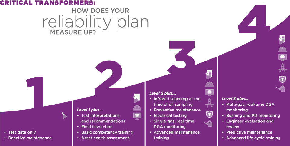
Figure 2
(click to enlarge)
|
||||||||||||||||||||||||||||||||||||||
Figure 3
Paper, Oil and Detectability
Kraft paper is the insulating material used to separate the copper windings in transformers. This provides mechanical and dielectric strength and dielectric spacing. The life of the transformer is based on the life of the paper. As paper degrades, the reliability of the unit degrades proportionately. It is essential to understand that the degradation of the paper is irreversible.
Dielectric fluid (mostly mineral oil) acts as a coolant, provides additional dielectric strength, protects the paper and plays a lead role in detecting problems in the transformer. The most fundamental action in transformer testing is a diagnostic testing of the fluid, regardless of its composition. Chemical testing is the accepted industry standard for detecting the reliability of a transformer.
Oil plus a catalyst like paper, copper and iron – coupled with an accelerator like heat and moisture – creates oxidation. The oxidation byproducts are numerous:
- Alcohols
- Peroxides
- Ketones Aldehydes
- Metallic Soaps
- Epoxies
The singlemost byproduct of oxidation that degrades paper significantly is acid. The following photos (in 750x magnification) show unacceptable levels of acids in paper.
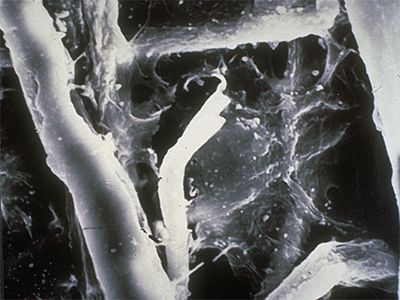
Figure 4
An acid level of 0.5 is considered the beginning of a Questionable level. Given that paper degradation cannot be reversed, a Questionable level of acid is the first sign that maintenance is required.
An acid level of 0.10 is considered to be the beginning of an Unacceptable result. Typical signs of this degradation level are the buildup of the acid along the fiber strand and the beginning of splitting within the strand is shown.
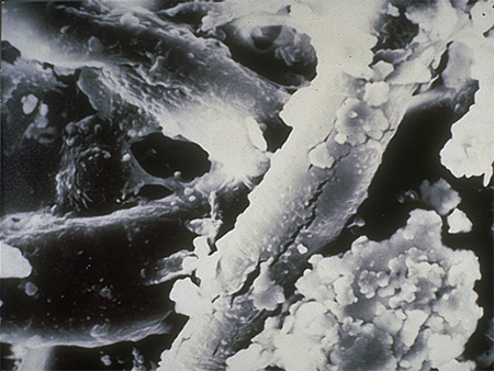
Figure 5
An acid level of 0.15 shows even more paper degradation and acid build up. Fiber strands are breaking and acids continue to accumulate.
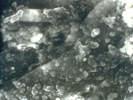
Figure 6
At an acid level of 0.30, the paper begins to look more like porridge than paper. Much of the dielectric strength is lost, and the life of this paper does not bode well for the reliability of the transformer.
Additional chemical testing for greater diagnostics are:
- Liquid screen
- Inhibitor content power factor
- Karl Fischer (moisture)
- Gas in oil (DGA), Metals in oil
- Furan
- PCBs (when appropriate)
Field Inspection
The value of a simple field inspection is often overlooked when sampling transformer fluids. A good visual inspection should look for and document the following:
- Area accessibility
- Paint condition
- Gaskets
- Bushings
Also the readings and accuracy of the following gauges should be checked:
- Level
- Temperature
- Pressure/Vacuum
Infrared and Chemical Testing Are Best Done Together
While IR testing is basically standard for electrical systems, the annual IR test is usually conducted for the entire facility, and the test of the transformer is seldom correlated to the time a fluid sample is pulled for the chemical analysis. Conducting a thorough IR scan at the time of fluid sampling provides better information for the IR and better information for oil analysis. This allows the engineering team to better identify the cause of a hotspot picked up on the IR report. Another benefit of coordinating IR with fluid sampling is that the resulting data can be integrated with the chemical data. Should there be an issue, this avoids the need to search for two sets of data that do not correlate because of the timing when each test was conducted.
Infrared scanning should focus on detecting…
- Temperature under 65°C/55°C
- Heat dissipation from top of the transformer tank/radiator to bottom of the transformer tank/radiator
- Low oil level
- Temperature difference between two similar bushings
- Hotspots showing on tank, LTC component, throat connections, or bushings
Preventive & Predictive Maintenance
One of the most disturbing trends in determining reliability is a tendency to ignore any sort of maintenance on transformers other than reactive maintenance. Considering the irreversible nature of paper degradation, it would seem logical to use diagnostic testing to determine the maintenance standards you will follow. In far too many cases – when conducting a Root Cause Analysis of a failed unit – the condition of the equipment prior to the failure was clearly documented as Questionable to Unacceptable, two ratings we use based on the specifics of the diagnostic tests. As shown in the acid photos, an acid level of between 0.5 and 0.10 is Questionable, and a level of more than 0.10 is Unacceptable.
In any reliability program, when equipment reaches these levels, the CMMS launches the process of addressing the issue in time to avoid a failure. One of the difficulties in doing so is because most CMMS and EAM programs do not have a built-in capability for transformers. As a result it is recommended that a more comprehensive data management program be installed to include transformer testing.
A good PM or PdM program includes:
- Vacuum Processing / Degassing
- Re-inhibiting
- Moisture Reduction
- Hot Oil Cleaning
- LTC Inspection and Repair
- Re-gasketing
- Refurbishing
- Full Electrical Testing
The impact of such testing services on transformer life is shown in Figure 7, Average Service Life Related to Number of Oil Services Performed. This study was based on more than 1,500 decommissioned units.
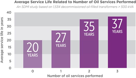
Figure 7
For the units in the study where no PM or PdM service was performed, the units survived for just under 20 years. This is what the insurance industry and many OEMs have predicted. But with just the performance of one service, the life was extended to more than 27 years. Two service procedures resulted in a life extension to just short of 35 years, and three services extended the life of the unit even further. It is without question that the life of a transformer can be doubled by properly maintaining the oil, removing moisture from the paper, and doing basic connection or bushing repairs. To summarize, a well-maintained unit is at a reduced level of risk and is much more likely to survive external faults than a poorly maintained one.
Fault Gas Monitoring
Transformer monitoring is a rapidly growing field. The market for DGA monitors is estimated to be more than $755 million by 2020. This includes expansion from predominantly utility and generation monitoring into wider and broader applications throughout the power grid. It is now common to purchase DGA monitors along with the purchase of a new transformer. Adding monitors to critical in-service transformers has become a significant component of transformer maintenance and reliability programs.
DGA monitor manufacturers use many different technologies for the purpose of dissolved gas detection in active monitoring. The largest manufacturers predominantly use gas chromatography (GC), photo-acoustic spectroscopy (PAS), and solid state (SS), thermal conductivity detector (TCD), or selective membrane (SM) based sensors. Other emerging DGA monitoring technologies include non-dispersive infrared (NDIR) and carbon nanotube (CNT).
SDMyers conducted an 18-month study that included all major OEM monitors that account for 95% of monitors in service. The study included monitor responses to fault simulations. Our findings are summarized as follows:
- The monitors worked. While there was some differences in lead and lag times for gas detection, overall DGA monitoring works well.
- There can be false positives. This requires diligence in understanding which data to avoid. However, when false positives are simply and routinely ignored, the level of risk to the unit is increased.
- Data management for monitor data can create data chaos. Correspondingly, most monitoring data is not integrated into the chemical, mechanical or electrical testing data.
- Hydrogen was present in every simulated fault condition, making the monitor an effective low-cost ‘check engine light’ of sorts. Running a chemical DGA after an alarm can then determine the precise nature of the events. Combining the DGA with the hydrogen monitor is suitable approach to transformer monitoring. There are certain transformer applications where multiple gas monitoring would be recommended, based on requirements for a broad range of gassing conditions and for transformers with a very high consequence from failure.
Summing Up
Without a well-planned oil service maintenance program, the risk from an unplanned fault either up or down line can result in substantial costs in both time and money. Yet with an astute, planned maintenance program, it is possible to nearly double the service life of the transformer. We would do well to remember the Risk/Reliability equation:
| Risk of failure = | Productivity x Consequences |
| Detectability |
About the Author
 Alan Ross of SDMyers is responsible for developing and executing long-term reliability strategies and next-generation leadership for all domestic and international operating units. He often presents at industry conferences and has authored two books, Unconditional Excellence and Beyond World Class. He completed his undergraduate degree in Mechanical Engineering at Georgia Institute of Technology and an MBA in Marketing from Georgia State University, graduating Magna Cum Laude. Alan is a Certified Reliability Leader, SMEP designee to the DOE’s Strategic Transformer Reserve task force and a member of the IEEE Reliability Society.