
ABSTRACT
Although the reliability of power to Industry is high, momentary power interruptions and voltage sags still occur. These may be caused naturally, by lightning strikes , snow storms and over grown vegetation or artificially, by heavy load switching, short circuits and automatic reclosing.
As these interruptions are generally less than one second in duration, most industrial installations and plants are able to ride through such power dips by virtue of their electrical and mechanical inertia. This is not the case with electrically held-in contactors and relays which control the machinery. These usually drop out after a few milliseconds, and as a result, the plant or process has to be restarted.
This paper presents the use of voltage dipproofing to provide ride-through for facilities using a specific technique and specially developed equipment. The effectiveness of this technique on associated equipment is discussed.
I. INTRODUCTION
An interconnected power system, by its very nature , will under normal conditions experience short duration voltage sags and momentary interruptions.
A voltage sag is a partial reduction in RMS Voltage that usually lasts from 0.5 to 30 cycles. A momentary interruption is a complete loss of AC power which can be 0.5 cycles to minutes in duration.
They may occur naturally as a result of lightning strikes on high tension lines, flash-overs caused by fires under the line, dirty insulators or salt build up on insulators, snow storms, overgrown vegetation or animals. Automatic reclosures clear such faults but have to interrupt the line for some hundreds of milliseconds. Heavy load switching, large load starting and automatic re-closures are the most common artificial causes.
With the advent of the digital economy equipment and process sensitivity to short duration voltage sags has increased significantly. The microprocessors and industrial control equipment that drive this economy are subjected to 20-30 of these sags per year. These Power Quality (PQ) events lead to costly process and economic disruptions which are costing the US economy over $150 Billion per year in lost productivity.
The extent of the problem needs to be determined, the sensitivity of the equipment that requires support will be evaluated, a solution will be proposed and a few applications selected.
II. EXTENT OF THE PROBLEM
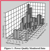
Extensive power quality studies have been conducted on the distribution systems in the United States. Figure 1 is a typical plot of this recorded data. A number of points can be highlighted from this data. It can be seen that a distribution customer is subjected to over 50 events per year where the voltage drops below 90% of nominal and that great majority of voltage sags last 10 cycles or less and were 20-30% in magnitude. This statistical data can be used as a guide by the distribution customer but it must be noted that the system performance can vary significantly from one part of the country to another as well as from one system to another. It must also be noted that distribution customers experience significantly more voltage sags and interruptions than customers fed directly from the transmission grid. However, faults almost anywhere in the power system can cause a momentary voltage sag that will last until the fault is cleared by the protection devices. In a transmission system it can take up to 6 cycles for the circuit breaker to open and clear the fault. In a distribution system it can take significantly longer to clear the fault depending on the settings of the over-current relays at the substation or fuse ratings on branch circuits.
However each case must be handled on a case by case basis and working with the local utility will prove invaluable in achieving the required solution performance.
III. IDENTIFYING EQUIPMENT SENSITIVITY
The sensitivity of equipment is the key component in evaluating the effect of voltage sags and interruptions at a facility. More and more data is becoming available but it is still not common practice to be able to easily obtain this sensitivity data for components used in the control systems at the facility. It can normally only be obtained by expensive testing or by trial and error.
A curve was developed by CBEMA (Computer And Business Equipment Manufacturers Association) as a reference for the ride through capability of data processing equipment. ITIC (The Information Technology Industry Council) have updated this curve. Figure 2. It shows that voltage sags below 70% of nominal will very likely affect the performance of the data processing equipment.
The semiconductor industry identified the importance of voltage sags on their industry and have recently introduced the Semi F47 standard that specifies the voltage sag immunity for semiconductor processing equipment. To date there is no such standard in industrial facilities and many actual facilities fall well short of the published ITIC curve. There are cases where existing equipment cannot handle voltage sags where the voltage drops below 80% and the o Measurlogic Inc. 2001 adjustable speed drives can trip when the voltage drops slightly to below 90% of nominal.
IV. CATEGORIZATION OF LOADS
In order to run a facility through power interruptions and sags, either the stored kinetic energy of the plant is utilized or standby power is supplied. Four levels of protection in order of increasing cost can be identified.
Feasibility and cost of implementing each solution depends on practicality, economics and the losses incurred due to downtime. The less expensive solutions are considered first.
Using the stored kinetic energy of the plant, only short interruptions, of one second or less, can be catered for. Considering that most voltage dips (approx. 90%) are of short duration, using the inertia of the plant is a distinct possibility. With the aid of individual monitoring studies and some ‘in-plant micro-surgery’, the sensitive equipment and controls can be identified and only these items protected, thereby reducing equipment and retrofit costs as well as enhancing reliability.
Next, the dynamic response of the electrical equipment in a plant is analyzed and divided into three distinct groups;
The desirability of maintaining motor connection as well as when to disconnect, needs to be evaluated and justified. Keeping the controls energized only solves part of the problem and the actual motors and drives must also be analyzed.
Rotating loads can be grouped into three categories:
Induction Motors
If the inertia of induction motors is used for dip-proofing, the motor can either be disconnected during a voltage dip or it can remain connected. If it is disconnected, no currents can flow in the stator and the existing magnetic field is maintained only by the rotor current.
Figure 3 shows a 75HP motor under load during a 280 millisecond open circuit. As the resistance of the rotor is very low, the flux will decay slowly and with it the residual voltage on the terminals. If the supply voltage is now reconnected and out of phase by more than 180 degrees, the rotor of the machine will first be decelerated to bring it into phase and then accelerated. Besides high voltages on the o Measurlogic Inc. 2001 windings and high inrush currents a very high torque of up to 15 times nominal can occur on the shaft which can damage it mechanically. Proposed standards recommend that the total residual voltage combined with the oncoming supply voltage should not exceed the rated voltage by more than 35%.
However, if a motor is kept connected during a voltage dip, current can still flow in the stator, either through other loads parallel to the motor or the secondary of the supply transformer. As current is flowing in the stator and the rotor torque develops that uses up the energy of the magnetic field and with it the voltage on the motor terminals will decrease much faster than in a disconnected motor.
Figure 4 : Flux decay of a 75HP during a 150msec short circuit
Voltage dips of 100msec and less are considered safe as the load and supply would not be significantly out of sync. Dips longer than 100msec have the effect of quickly reducing the induced voltage to acceptable levels, typically, the flux will decay rapidly to less than 30% of rated within 5 - 6 cycles thereby reducing the stress to the system. Figure 4.
Keeping the load connected is in most cases preferable to reconnecting it. In certain cases where the above methods are still deemed unsafe, more sophisticated methods, like synchronized re-switching, can be employed where the supply remains connected for a period of time, disconnected and then reconnected within a safe ‘window’.
Although low inertia drives can only be dipproofed for relatively short periods of time using their inherent inertia, a fairly large percentage of problems will still be overcome. For longer periods, external energy would have to be supplied in order to keep the drive running.
This is less of a concern when the voltage has only sagged and not been totally interrupted as the supply and load would still be synchronized.
Synchronous Motors
The second group is synchronous motor drives. They can also be dip-proofed by either removing the DC rotor field as fast as possible with the stator still connected, or disconnecting the stator and applying synchronized re-switching.
Adjustable Speed Drives
Adjustable speed drives can be divided into AC drives and DC drives. AC drives can be further divided into voltage driven and current driven types. Some, but not all, can tolerate voltage dips and various methods of providing ride-through can be considered.
The feasibility of each option will depend on practicality, economics and the type of drive installed. Briefly, they are as follows:
V. A SOLUTION
From the above, it becomes clear that the first thing to do to DIP-PROOF a plant is to supply the very low inertia equipment, i.e. controls, with standby power. The following specification applies.
The DPI - VOLTAGE DIP-PROOFING INVERTERTM is a capacitor based power conditioning device that can provide ride through capability for voltage sags and momentary power outages :
VI. THEORY OF OPERATION
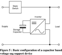
The basic configuration is shown in Figure 5 and the use of an off-line system dictated the design of ultra-fast circuitry to avoid sensitive control devices from dropping out or faltering during switch over.
The system consists of a static switch in series with the load, and an inverter parallel to it. For energy storage, capacitors are used.
Capacitors are available with high voltage ratings so that no transformers are necessary.
They need no maintenance and are, in general, much more reliable than batteries. The capacitors are only loaded during dips, they work under ideal conditions by being always charged and carrying no ripple current. Subsequently no heat is generated and they are hardly stressed. Predicted life-time is approximately 12 years at 25ºC/ 77ºF
The incoming sine wave is continuously monitored and should it deviate from the nominal value by a pre-determined percentage, the static switch is switched off and the inverter is switched on.
The voltage supplied by the inverter is synchronous with the supply voltage and is a stepped square wave. This wave shape has various advantages, firstly the RMS and the peak value is the same as that of a sine wave, it can therefore be used with transformers and coils where RMS is important and with electronic relays using capacitor input filters where peak voltage is required. It can supply any inductive load without being distorted and the RMS voltage is regulated.
The only power device that is constantly loaded is the static switch. This consists of a diode bridge and an IGBT transistor. Should they malfunction it is probable that they fail to short circuit and would therefore not ‘drop’ the load. The systems fails to safe in the event of a component failure to ensure that the load is never disconnected from the supply.
VII. APPLICATION EXAMPLES
The following section considers suitable applications and installations for this capacitor energy storage power condition solution.
If the pump or compressor is subjected to an outage of greater than 350msecs it is prudent that the supply is disconnected and remains so even if the supply returns. This will ensure that the compressor is not subjected to possible excessive mechanical stresses. However a voltage sag of up to 70% can be ridden through for a longer period with safety.
The DPI, with its two level option can achieve this. The DPI has two level sensing and ride through times.
Level 1 - The standard users adjustable settings.
Level 2 - A fixed timer set to 200msecs triggered when the supply drops to 30% of nominal.
This allows the DPI to function on the Level 1 settings for sags down to 30% of nominal but for sags below 30% or for an outage the DPI will drop the load after 200msecs or rest to normal operation if the supply recovers before the time out.
Any process that is affected by a momentary sag or outage is a possible candidate for this capacitor based power conditioning solution.
These would include but not limited to :
VIII. CONCLUSION
Providing ride-through for facilities is obviously not a simple task. Using the methods described in this paper involve more than just the installation of a ‘black box’ to support the system. The interaction between the controlling equipment and sensors, motors and drives along with power quality monitoring reports and studies needs to be evaluated before implementation can begin. Although this requires a combined effort from involved parties, investment return should be realized in a relatively short period of time and the costs involved are usually considerably lower than implementing huge and expensive solutions to protect an entire facility. "
IX. REFERENCES
[1] “Applied Electronics In The Field Of Voltage Dip-Proofing” by F.V. Fischer, 1992
[2] “The Effects Of Voltage Dips On Induction Motors” by M.D. McCulloch, 1992
[3] “Distribution Power Quality Monitoring Data” - EPRI, 1994
Although the reliability of power to Industry is high, momentary power interruptions and voltage sags still occur. These may be caused naturally, by lightning strikes , snow storms and over grown vegetation or artificially, by heavy load switching, short circuits and automatic reclosing.
As these interruptions are generally less than one second in duration, most industrial installations and plants are able to ride through such power dips by virtue of their electrical and mechanical inertia. This is not the case with electrically held-in contactors and relays which control the machinery. These usually drop out after a few milliseconds, and as a result, the plant or process has to be restarted.
This paper presents the use of voltage dipproofing to provide ride-through for facilities using a specific technique and specially developed equipment. The effectiveness of this technique on associated equipment is discussed.
I. INTRODUCTION
An interconnected power system, by its very nature , will under normal conditions experience short duration voltage sags and momentary interruptions.
A voltage sag is a partial reduction in RMS Voltage that usually lasts from 0.5 to 30 cycles. A momentary interruption is a complete loss of AC power which can be 0.5 cycles to minutes in duration.
They may occur naturally as a result of lightning strikes on high tension lines, flash-overs caused by fires under the line, dirty insulators or salt build up on insulators, snow storms, overgrown vegetation or animals. Automatic reclosures clear such faults but have to interrupt the line for some hundreds of milliseconds. Heavy load switching, large load starting and automatic re-closures are the most common artificial causes.
With the advent of the digital economy equipment and process sensitivity to short duration voltage sags has increased significantly. The microprocessors and industrial control equipment that drive this economy are subjected to 20-30 of these sags per year. These Power Quality (PQ) events lead to costly process and economic disruptions which are costing the US economy over $150 Billion per year in lost productivity.
The extent of the problem needs to be determined, the sensitivity of the equipment that requires support will be evaluated, a solution will be proposed and a few applications selected.
II. EXTENT OF THE PROBLEM
Extensive power quality studies have been conducted on the distribution systems in the United States. Figure 1 is a typical plot of this recorded data. A number of points can be highlighted from this data. It can be seen that a distribution customer is subjected to over 50 events per year where the voltage drops below 90% of nominal and that great majority of voltage sags last 10 cycles or less and were 20-30% in magnitude. This statistical data can be used as a guide by the distribution customer but it must be noted that the system performance can vary significantly from one part of the country to another as well as from one system to another. It must also be noted that distribution customers experience significantly more voltage sags and interruptions than customers fed directly from the transmission grid. However, faults almost anywhere in the power system can cause a momentary voltage sag that will last until the fault is cleared by the protection devices. In a transmission system it can take up to 6 cycles for the circuit breaker to open and clear the fault. In a distribution system it can take significantly longer to clear the fault depending on the settings of the over-current relays at the substation or fuse ratings on branch circuits.
However each case must be handled on a case by case basis and working with the local utility will prove invaluable in achieving the required solution performance.
III. IDENTIFYING EQUIPMENT SENSITIVITY
The sensitivity of equipment is the key component in evaluating the effect of voltage sags and interruptions at a facility. More and more data is becoming available but it is still not common practice to be able to easily obtain this sensitivity data for components used in the control systems at the facility. It can normally only be obtained by expensive testing or by trial and error.
A curve was developed by CBEMA (Computer And Business Equipment Manufacturers Association) as a reference for the ride through capability of data processing equipment. ITIC (The Information Technology Industry Council) have updated this curve. Figure 2. It shows that voltage sags below 70% of nominal will very likely affect the performance of the data processing equipment.
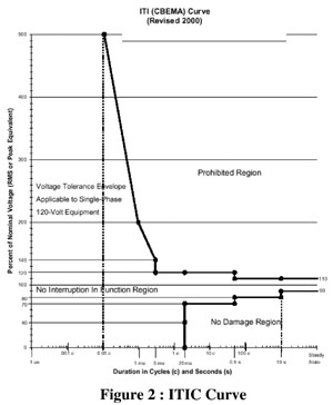
The semiconductor industry identified the importance of voltage sags on their industry and have recently introduced the Semi F47 standard that specifies the voltage sag immunity for semiconductor processing equipment. To date there is no such standard in industrial facilities and many actual facilities fall well short of the published ITIC curve. There are cases where existing equipment cannot handle voltage sags where the voltage drops below 80% and the o Measurlogic Inc. 2001 adjustable speed drives can trip when the voltage drops slightly to below 90% of nominal.
IV. CATEGORIZATION OF LOADS
In order to run a facility through power interruptions and sags, either the stored kinetic energy of the plant is utilized or standby power is supplied. Four levels of protection in order of increasing cost can be identified.
- The installation of equipment with ridethrough facility already incorporated.
- Identifying the sensitive equipment and controls of the plant and upgrading their ridethrough capabilities.
- The provision of stand-by power for the entire plant.
- The use of a utility solution such a new nearby substation or a new feeder system.
Feasibility and cost of implementing each solution depends on practicality, economics and the losses incurred due to downtime. The less expensive solutions are considered first.
Using the stored kinetic energy of the plant, only short interruptions, of one second or less, can be catered for. Considering that most voltage dips (approx. 90%) are of short duration, using the inertia of the plant is a distinct possibility. With the aid of individual monitoring studies and some ‘in-plant micro-surgery’, the sensitive equipment and controls can be identified and only these items protected, thereby reducing equipment and retrofit costs as well as enhancing reliability.
Next, the dynamic response of the electrical equipment in a plant is analyzed and divided into three distinct groups;
- Very low inertia; the controls. Typically contactors, relays, PLC’s, electronic relays and similar sensitive auxiliary equipment. In general all controls either drop out or switch off within a 5 to 30 millisecond (0.5 to 2 cycles) period.
- Low inertia; motors and drives. Compressors or positive displacement pumps may drop in speed to a level where they have to be switched off within approximately 350 milliseconds. Small motors driving spinning or CNC machines could also come to a standstill within this period.
- High inertia; motors and drives. Conveyers and fans can run for seconds after the power is removed.
The desirability of maintaining motor connection as well as when to disconnect, needs to be evaluated and justified. Keeping the controls energized only solves part of the problem and the actual motors and drives must also be analyzed.
Rotating loads can be grouped into three categories:
- Induction Motors
- Synchronous Motors
- Adjustable Speed Drives
Induction Motors
If the inertia of induction motors is used for dip-proofing, the motor can either be disconnected during a voltage dip or it can remain connected. If it is disconnected, no currents can flow in the stator and the existing magnetic field is maintained only by the rotor current.
Figure 3 shows a 75HP motor under load during a 280 millisecond open circuit. As the resistance of the rotor is very low, the flux will decay slowly and with it the residual voltage on the terminals. If the supply voltage is now reconnected and out of phase by more than 180 degrees, the rotor of the machine will first be decelerated to bring it into phase and then accelerated. Besides high voltages on the o Measurlogic Inc. 2001 windings and high inrush currents a very high torque of up to 15 times nominal can occur on the shaft which can damage it mechanically. Proposed standards recommend that the total residual voltage combined with the oncoming supply voltage should not exceed the rated voltage by more than 35%.
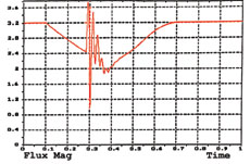
Figure 3 : Flux decay of a 75HP motor under a 280msec open circuit
However, if a motor is kept connected during a voltage dip, current can still flow in the stator, either through other loads parallel to the motor or the secondary of the supply transformer. As current is flowing in the stator and the rotor torque develops that uses up the energy of the magnetic field and with it the voltage on the motor terminals will decrease much faster than in a disconnected motor.
Figure 4 : Flux decay of a 75HP during a 150msec short circuit
Voltage dips of 100msec and less are considered safe as the load and supply would not be significantly out of sync. Dips longer than 100msec have the effect of quickly reducing the induced voltage to acceptable levels, typically, the flux will decay rapidly to less than 30% of rated within 5 - 6 cycles thereby reducing the stress to the system. Figure 4.
Keeping the load connected is in most cases preferable to reconnecting it. In certain cases where the above methods are still deemed unsafe, more sophisticated methods, like synchronized re-switching, can be employed where the supply remains connected for a period of time, disconnected and then reconnected within a safe ‘window’.
Although low inertia drives can only be dipproofed for relatively short periods of time using their inherent inertia, a fairly large percentage of problems will still be overcome. For longer periods, external energy would have to be supplied in order to keep the drive running.
This is less of a concern when the voltage has only sagged and not been totally interrupted as the supply and load would still be synchronized.
Synchronous Motors
The second group is synchronous motor drives. They can also be dip-proofed by either removing the DC rotor field as fast as possible with the stator still connected, or disconnecting the stator and applying synchronized re-switching.
Adjustable Speed Drives
Adjustable speed drives can be divided into AC drives and DC drives. AC drives can be further divided into voltage driven and current driven types. Some, but not all, can tolerate voltage dips and various methods of providing ride-through can be considered.
The feasibility of each option will depend on practicality, economics and the type of drive installed. Briefly, they are as follows:
- The use of a “Phase Loss Detector” to automatically restart drives which have instantaneous trip circuitry:
These drives include a very sensitive phase loss detection circuit which shuts the drive off in less than 10 milliseconds. The detector with a response time of approx. 10 milliseconds or better would, upon phase loss detection, send a signal to the drive logic or controlling PLC. This would in turn reissue a command to the drive to automatically restart and as a result, would not slow down significantly or trip off line. - The support of the control circuitry andpower supplies within the drive, (assuming the lack, or modification of, the 3-phase loss detection and trip circuit):
These drives can be “Dip-Proofed”. - The bypass of the power loss detection and trip circuitry:
This requires careful investigation and should only be considered if damage is unlikely and/or warranties will not be voided. This will apply to older drives and has been implemented on plastic extrusion line drives. - The addition of increased energy storage capacity on the DC bus to provide ride-through:
This can be achieved by adding extra capacitors on the DC side of the rectifier in the drive. The auxiliary or regulator supplies will probably also need support. - The exchange of older drives for newer ones with limited ride-through:
Instead of tripping and switching off, some newer drives are able to re-synchronize their output with the spinning load. This option is only feasible if the duration of the voltage dips is around 500 milliseconds as most manufacturers only offer an average published ride-through of around o second - The addition of a ride-through device specifically designed for drive applications:
Such devices may only be cost effective when used to protect larger drives and depending on their design, are not suitable for total interruptions, only sags.
V. A SOLUTION
From the above, it becomes clear that the first thing to do to DIP-PROOF a plant is to supply the very low inertia equipment, i.e. controls, with standby power. The following specification applies.
- The ability to handle highly inductive loads as they are made up mainly of electromagnetic devices.
- The ability to withstand the inrush or energizing current of contactors, starters and relays which can be up to 10 times the holding current.
- Inherent reliability is of utmost importance as failure of the device would mean involuntarily shutting down the plant. For this reason an “Off Line” system was chosen.
- The device is only required to run for short periods of time.
- The device should be maintenance free. If adjustment or routine testing is required, it must be possible to by-pass it without dropping the switch-board and load.
- The device should be small, light weight and easy to install in new or existing switchboards.
- The incorporation of an adjustable timer to provide ‘pre-set’ ride through to loads deemed unsafe to keep connected beyond a certain point.
The DPI - VOLTAGE DIP-PROOFING INVERTERTM is a capacitor based power conditioning device that can provide ride through capability for voltage sags and momentary power outages :
- Reliability: The MTBF (mean-time-betweenfailures) is two to three times better than with similar devices. This is the result of using an off-line method, where the inverter is on stand-by until a voltage-dip occurs. Losses develop only over the static switch making the unit 98% efficient. A fail-to-safety design approach enhances the reliability.
- Maintenance: By using capacitors as energy storage devices, battery maintenance and hazardous waste disposal is eliminated. Typical voltage sag characteristics also tend to reduce battery life dramatically. This method is ideal for ultra clean environments where gaseous emissions can not be tolerated.
- Support of multiple sags or outages: The capacitor energy storage is able to be recharged within 1 second which allows support for multiple sags or outages which occur in quick succession.
- Inrush currents: The unit can tolerate between 10 and 20 times the nominal current. When choosing the correct size inverter, only the holding VA or continuous current needs to be considered.
- Speed: An ultra-fast transfer time of approx. 700 microseconds prevents extremely sensitive relays, starters, contactors and PLC’s from dropping out.
- Low power factor tolerance: In contrast to normal UPS’s which specify power factors of 0.7 or higher, the DPI is well suited to drive switchboards which generally have a power factor of 0.15 to 0.4.
- Size: A 3kVA 120V unit measures only 21.84in x 12.25in x 6.4in. Using capacitors for energy storage, batteries are eliminated and the DC voltage can be kept high which eliminates the need for transformers.
- Easy installation: only three terminals have to be connected. Status monitors in the form of LED indicators.
- Accurate application control: All units incorporate a timer adjustable from 0.1 seconds to 3.1 seconds and offer a transfer level variable from 55% to 90% of nominal supply voltage.
- Industrial Robustness: Unit has been designed specifically for operation in harsh environments and therefore has a robust enclosure and does not require ventilation
VI. THEORY OF OPERATION
The basic configuration is shown in Figure 5 and the use of an off-line system dictated the design of ultra-fast circuitry to avoid sensitive control devices from dropping out or faltering during switch over.
The system consists of a static switch in series with the load, and an inverter parallel to it. For energy storage, capacitors are used.
Capacitors are available with high voltage ratings so that no transformers are necessary.
They need no maintenance and are, in general, much more reliable than batteries. The capacitors are only loaded during dips, they work under ideal conditions by being always charged and carrying no ripple current. Subsequently no heat is generated and they are hardly stressed. Predicted life-time is approximately 12 years at 25ºC/ 77ºF
The incoming sine wave is continuously monitored and should it deviate from the nominal value by a pre-determined percentage, the static switch is switched off and the inverter is switched on.
The voltage supplied by the inverter is synchronous with the supply voltage and is a stepped square wave. This wave shape has various advantages, firstly the RMS and the peak value is the same as that of a sine wave, it can therefore be used with transformers and coils where RMS is important and with electronic relays using capacitor input filters where peak voltage is required. It can supply any inductive load without being distorted and the RMS voltage is regulated.
The only power device that is constantly loaded is the static switch. This consists of a diode bridge and an IGBT transistor. Should they malfunction it is probable that they fail to short circuit and would therefore not ‘drop’ the load. The systems fails to safe in the event of a component failure to ensure that the load is never disconnected from the supply.
VII. APPLICATION EXAMPLES
The following section considers suitable applications and installations for this capacitor energy storage power condition solution.
- Semiconductor wafer manufacturing:
In order to address the impact of voltage sags on semiconductor manufacturing, The semiconductor industry formulated the SEMI F47 standard for Voltage ride through of semiconductor tools. This standard requires semiconductor tools to operate within a specified input AC line voltage vs. time profile. This SEMI F47 curve closel represents the power quality experienced at a typical semiconductor fabrication facility. Capacitor based ride through devices are very suitable for the voltage support of individual components eg. Vacuum pump controls, or processes within the tool ensuring a cost effect and reliable solution for existing or new installations. The DPI exceeds the requirements of SEMI F47 as it can withstand a complete outage for up to 3.1 seconds. - Plastic pipe extrusion plant:
Plastic extruders have a wide range of controls associated with them including AC or DC drives, PLC’s as well as numerous control relays, solenoid valves etc. The associated cost when a line trips because of an outage can run from $10-60k per outage caused by down time, scrap product and cleaning of the system before being able to restart. If the plant experiences numerous dips within a short period, conventional battery life was diminished drastically. Maintenance and replacement can also become a nuisance. - Large Pump or Compressor applications:
Large pumps and compressors offer a challenge when it comes to maximizing voltage ride through capabilities for both Voltage Sags and momentary outages.
The DPI can be used as a single solution or multiple units can be used depending on the number of controls that need to be supported during a voltage sag or momentary interruption.
If the pump or compressor is subjected to an outage of greater than 350msecs it is prudent that the supply is disconnected and remains so even if the supply returns. This will ensure that the compressor is not subjected to possible excessive mechanical stresses. However a voltage sag of up to 70% can be ridden through for a longer period with safety.
The DPI, with its two level option can achieve this. The DPI has two level sensing and ride through times.
Level 1 - The standard users adjustable settings.
Level 2 - A fixed timer set to 200msecs triggered when the supply drops to 30% of nominal.
This allows the DPI to function on the Level 1 settings for sags down to 30% of nominal but for sags below 30% or for an outage the DPI will drop the load after 200msecs or rest to normal operation if the supply recovers before the time out.
Any process that is affected by a momentary sag or outage is a possible candidate for this capacitor based power conditioning solution.
These would include but not limited to :
- Chemical processing plants
- Lubrication pump controls
- Submersible pumps
- Crushers Blowers Foundries
- Adhesive manufacture
- Printing
- Paperboard and box manufacture
VIII. CONCLUSION
Providing ride-through for facilities is obviously not a simple task. Using the methods described in this paper involve more than just the installation of a ‘black box’ to support the system. The interaction between the controlling equipment and sensors, motors and drives along with power quality monitoring reports and studies needs to be evaluated before implementation can begin. Although this requires a combined effort from involved parties, investment return should be realized in a relatively short period of time and the costs involved are usually considerably lower than implementing huge and expensive solutions to protect an entire facility. "
IX. REFERENCES
[1] “Applied Electronics In The Field Of Voltage Dip-Proofing” by F.V. Fischer, 1992
[2] “The Effects Of Voltage Dips On Induction Motors” by M.D. McCulloch, 1992
[3] “Distribution Power Quality Monitoring Data” - EPRI, 1994