Introduction – What is IEC 61850?
When asked the question “what is IEC 61850?” most people would respond “an automating protocol”. Although this is part of the answer, a better answer would be “a comprehensive way to look at all aspects of an automation system”. The experts who designed IEC 61850 wanted to optimize the automation system over the full life cycle of these systems, not just the operational period. This broad view resulted in best-practice answers to the questions:
- What is an automation system?
- How much environmental hardening of devices is needed?
- How do you design an optimal automation system? How can we validate this design?
- What performance parameters are needed to operate an automation system?
- How to assemble an automation system from piece parts?
- Which abstract services and models are needed by automation system?
- How do we implement these models and services on real devices?
- How do we validate the as-built automation system against the design goals?
- How do we do all this using a standards-based approach (not re-invent the wheel)?
- What are the best practices in the design of automation systems?
If you are an expert in IEC 61850, you will recognize that the above list follows (in order) the sections of IEC 61850 except for 61850-2 which is the glossary; whereas the ‘automation protocol’ portion is only the highlighted bullet above.
What is an automation system?
Before discussing IEC 61850, we need to define exactly what is an automation system. The normal vague answer “a collection of hardware and software used to monitor, control, and protect a process”. This appears to be a reasonable definition, but it is not precise enough to lead to an optimal implementation. For the purposes of this paper, an automation system is “a system used to monitor, control, and protect a process which has been optimize over the lifetime of the process”. There are 2 key points which have been added:
- Some optimization function has been applied to the design
- The lifetime of the controlled process is explicit
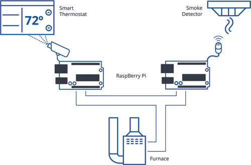
To clarify our thoughts, a simple automation system will be considered. Figure 1 shows a simple automation system. The system consists of a temperature sensor, smoke detector, and a furnace. The objective is to enable the furnace when the temperature is below the setpoint and disable the furnace when the smoke level is above the setpoint.

Figure 1 - Automation system before integration
One way to design this system is to purchase a thermostat, a smoke detector, and a furnace then ‘integrate the system.’ We purchase a wireless smart ZigBee thermostat, a wall-mounted smoke detector, and a furnace designed for a wired thermostat. All we do is integrate the automation system.
Our first problem is that the thermostat and furnace use incompatible protocols. We can fix that by purchasing a camera and also purchase a Raspberry Pi kit with one relay output; then just apply some custom software to convert the picture of the thermostat display into a contact output (very easy!).
Next problem is that the smoke detector protocol (audio output) is incompatible with everything else. We just need to buy another Raspberry Pi kit with a microphone input which converts the sound to a contact opening. Wire this in series with the other Raspberry Pi kit then wire to the furnace.
Now it is time to test the system. Because it is summertime and daylight, we assign a low temperature setpoint and we find that the furnace turns on, so we are done. Discard all the packaging (and instructions and wiring diagrams and source code) because the integration test was successful. Figure 2 shows the resulting system.

Figure 2 – Automation system after initial integration
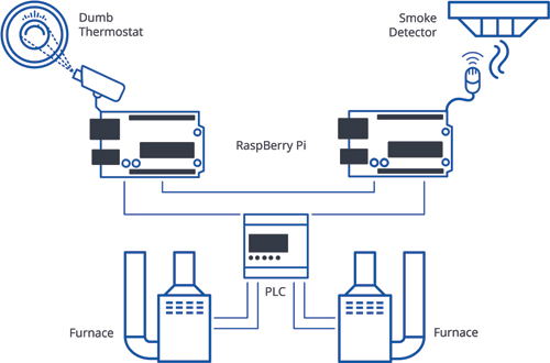
Four months later, the house gets cold at night. We forgot that the thermostat display has no backlight. Simple enough to fix, just leave the lights on at all times (and pay for the extra power to run the light).
Two months later, the house gets cold even during the day. We forgot to buy a large enough furnace, need to buy another one. But now we cannot control both furnaces from a single contact closure. So we buy a Programmable Logic Controller with one input and two outputs. Program the controller and now we have a warm house.
A few years later, the thermostat malfunctions and the replacement has a different display style. No problem, just modify the Raspberry Pi code… where did we put that source code? Figure 3 illustrates the final system.

Figure 3 – Final Automation system after system upgrade
The above is a classical non-optimized design. Where did we go wrong? IEC 61850 can help us.
IEC 61850 Application Domains
IEC 61850 principles have been applied in many areas. There is no need to use all parts of the standard. In many cases, only parts of the standard have been applied with great success. For example, 61850-3, Quality Requirement and Environmental Conditions, has been applied to design and specify equipment for harsh environments such as electrical substations. In other cases, many parts of IEC 61850 are used to build automation systems for industrial plants. Sometimes, all parts of IEC 61850 are used to “future-proof” automation systems such as those in electrical transmission switching stations.
The data modeling principles of IEC 61850 have been applied for requirements analysis of automation systems (possibly implemented using protocols such as DNP3/IEEE 1815).
The resulting automation systems have been used for industrial process control, co-generation, wind turbine plants, hydro-electric generators, and electrical substation systems.
Referenced Standards
IEC 61850 is built upon the premise that existing open standards should be used throughout 61850. Wherever possible, existing standards are referenced in an un-modified form, and this allows vendors and users to build products and systems which are fully compatible with other systems. For example, at the networking layer, IEC 61850 specifies IEEE 802 standard without modification or extension. A partial list of referenced standards includes:
- IEC 62351 – Security protocols
- IEC 81346 – Signal Naming
- RFC xxx – TCP/IP protocol suite and IP-based time sync (SNTP)
- ISO/IEC 8xxx and 9xxx –OSI protocol suite
- ISO 9506 – Manufacturing Messaging Services (MMS)
- ISO/IEC 8824-1 – Abstract Syntax Notation (ASN.1)
- ISO/IEC 8825-1 – ASN.1 encoding using Basic Encoding Rules (BER)
- IEEE 802 and ISO/IEC 8802 – Ethernet standards
- IEC 61869-9 – Instrument transformers
- IEC 62439-3 – Link redundancy protocols
- IEEE 1588 and IEC 61588 – Precision Time Protocol
- IEC 61000-4-x – Electromagnetic compatibility (surge, emissions, etc.)
- IEC 60870-2-x – Environmental conditions (temperature, seismic, altitude, vibration, etc.)
- IEEE C37.90.x – RF immunity
- Etc.
As can be seen from this list, IEC 61850 lets other standards define many of the ‘protocols,’ so suggesting that IEC 61850 is “just another protocol” is a wrong statement because most of the protocols are defined outside of IEC 61850.
Under-appreciated part of IEC 61850
The IEC 61850 standard should be required reading for everyone involved in power automation projects. It should be suggested reading for everyone involved in any kind of automation project The standard explains how to THINK about project development in general. It can be thought of as a step-by-step cookbook of items to consider before any purchasing decisions have been made.
IEC 61850-4 (System and Project Management Including Testing), reminds us that functional decomposition of a system is the first step in any design. This then drives requirements which is the basis of the automation project. Documentation is a key part of the design because automation systems often survive the memories of those responsible for the project. It is also important when the automation requirements change during the lifetime of the system.
IEC 61850-6 (System Configuration Language) defines a method to automate the system design and configuration of the devices that make up a system. The key concept is that a unified language is used throughout the process from functional specification, assignment of functions to devices, device configuration, intra-device signal flow, inter-device signal flow, primary equipment connectivity, and communication-level connectivity. This results in a single file containing most of the details of the as-built automation system. The power of this approach is that this same file (System Configuration Description) can be used to generate project reports such as an overall one-line graphic, graphics used on protective relay faceplates, and asset lists. Because the language is extensible, it can also be used to document information such as the geographic position of primary equipment (“the breaker is over there”), commissioning test results, and also be used to configure equipment simulators during maintenance.
IEC 61850-10 – Conformance Testing defines a method to determine whether the components of the automation system are compliant to the standard. For this purpose, a component is required to be accompanied by a mandatory set of documents which formally declare the capability. Using this formal definition, a test plan can be developed to test each of the declared capabilities either as static tests (is it in the instruction manual?) or dynamic tests (does it respond properly given a specific stimulus). Additionally, this section defines how to measure the performance parameters (how fast does it do …”) specified in the formal documents. These formal documents can also be provided to potential customers to assist them in vendor selection without requiring reading thousands of pages of device documentation. This part is valuable to determine HOW formal documentation can be created for any type of device.
Applying IEC 61850 – Operational Phase
IEC 61850 concepts can be considered when designing any automation system. A few examples will illustrate IEC 61860 applications.
Time synchronization is important to every automation system. The requirements for the resolution and accuracy of the timestamp depends upon the specific application within the automation system. IEC 61850-5 provides guidance for the time synchronization requirements. In many cases, these requirements span orders of magnitudes; some parts needing highly accurate timestamps (such as raw samples of the AC analog values) and some low accuracy timestamps (such as times when breaker closures are made). For this reason, IEC 61850 defines a common SNTP synchronization mechanism and allows others such as PTP and IRIG-B to be layered on top for additional synchronization requirements. From a system perspective, there are many good reasons to perform the time synchronization over the same Ethernet LAN as other communication.
The concept of a process bus is central to 61850 applications. Process bus connects the “field I/O” to the automation equipment. This includes periodic samples (using Sampled Values from 61850-9-2) as well as aperiodic data (GOOSE from 61850-8-1). The UCAIug has defined an easy-to-use “Merging Unit” which emits 61850-9-2 sampled values with very few options.
Synchrophasors are used in advanced measurement applications. These are high-speed measurements of the magnitude and angle of the sinusoidal waveforms. IEC 61850 simply treats these as “normal” Sampled Values. Synchrophasor measurements have quickly become necessary components for analysis at both the local and wide-area levels.
IEC 61850 is now publishing standards to extend the periodic and aperiodic sampling from the LAN to the WAN to allow wide-area measurements. These will be specified in 61850-8-1 and 61850-9-2 as the “Routable GOOSE” and “Routable Sampled Values” which send the measurements over standard IP-based communication protocols.
IEC 61850 can be applied during the design phase to help decide which data is needed for various parts of the automation system. This then drives the selection of sensors needed to provide that data. IEC 61850-6 Configuration Language can ensure that every needed signal is produced somewhere in the automation system.
Applying IEC 61850 – Engineering Phase
IEC 61850 also finds use during the concept development and detailed engineering phases. IEC 61850-3 provides a single-source best-practice document for the creation of hardened devices. Users should consider that the additional cost to comply with these stringent standards will often pay back many times with increased reliability and lower long-term maintenance costs.
IEC 61850-6 allows documentation at the specification, as-designed, and as-built phases. This documentation can be converted into a wide variety of manager-friendly formats for both post-project analysis and studies of extensions to the automation system.
One example of this is the System Specification Description (SSD) file which describes WHAT the automation system is to accomplish without reference to any real automation equipment. This allows the file to be used as a vendor-independent procurement document.
Upon completion of the detailed engineering, it is useful to determine if the system requirements have actually been met. IEC 61850-4 and IEC 61850-10 can be used to make this determination.
Getting Started
One of the main problems with IEC 61850 is that it includes almost every aspect of automation design. It can be difficult to determine where to begin the journey of IEC 61850. The first place to begin is to fully understand WHAT to automation system is expected to accomplish. Although it seems obvious, this is not always the starting point for many projects. Once this is well understood, IEC 61850 can be read in small sections. The best way to accomplish this is to concentrate on the narrative and ignore the detailed tables and figures and charts. IEC 61850 is a very readable document but the details are not always important for a first-pass understanding. After reading the standard, several high-level articles on 61850 should be read to reinforce key concepts. You must then decide which types of communication need to be used in the automation system, not all must be used together.
One common failing of many IEC 61850 projects is to ignore the standard as a planning tool. Once the automation system goals have been established, these goals must be coded into a System Specification Tool (SST) as described in IEC 61850-6 for a high-level analysis of what signals will be needed. After this, a trial mapping onto real devices using the System Configuration Tool (SCT) described in IEC 61850-6 can be used. This will show gaps in the understanding of the automation system. Iterating with these tools until a workable automation design is accomplished should be done before any purchasing decisions are made. The formal specification descriptions can then be applied to the procurement stage after which the real devices can be integrated using the 61850-6 tools.
Note that none of this above description is dependent upon actually using the IEC 61850 protocols in the final system. A DNP3 system can be developed using the same IEC 61850 methodology.
Summary
This paper has introduced IEC 61850 as much more than a protocol with emphasis on the structured design of automation systems. The original example of a less-than-optimal design can now be visited again.
Where did we go wrong? Our first error was to emphasize the pieces of the automation system without understanding the underlying process. The actual goal was to keep our house warm and safe but we lost that goal by first making assumptions and purchasing equipment from those assumptions. If we took the time to analyze the entire system, we would have started with the communication requirements: the furnace need to know when it should be enabled. An analysis of the signals from the transducers would have clearly shown that there was no compatible source. Documentation of the system goals and the low-level documentation (source code for the microcontrollers) was not maintained according to 61850-4 and even the environmental requirements for the sensors was not taken into account. Lastly, the test plan for the completed system was inadequate for the needs of the user. Using a IEC 61850-based approach would have resulting in a simpler, less expensive system with easy upgrade paths; and saved a lot of time, effort, and money.
Conclusion
IEC 61850 is much more than a communication protocol, it is a “way of life” in the design and construction of automation systems. The MMS / BER protocol is actually one of the least important outcomes of the IEC 61850 standard. Many automation experts have devoted thousands of hours into the concepts of automation protocols; ignoring their collective wisdom is ill-advised.
IEC 61850 is influencing many existing protocols such as DNP3 with the concept of hierarchical data modeling. DNP3-XML configuration language was strongly influenced by concepts in IEC 61850-6. Systems have been designed using IEC 61850 but then implemented using other standards. Using IEC 61850 in the “legacy” environments allows a simplification of the system design and a much more robust set of documentation.
Lastly, the IEC 61850 protocols have been designed to co-exist with other protocols which means that mixed environments are easily possible. A simple example of this is DNP3 with GOOSE communications.
IEC 61850 presents an evolution of the design of automation systems from ad-hoc to very structured. These concepts can be re-used outside of the electrical substation environment.
About the Author
 Bruce Muschlitz is a Research Engineer at NovaTech with more than 20 years experience in project leadership and utility communications protocols. He is heavily involved with industry/ national/international standards groups and chairs the UCAIug testing committee which is responsible for maintenance of the IEC 61850 device conformity testing program.
Bruce earned a MS in Electrical Engineering from Lehigh University. He is a senior member of IEEE, as well as, a member of the DNP3 Technical Committee, UCA International Users Group Technical, a member of IEC TC 57 on working groups 10 (IEC 61850) and 17 (Distributed Energy Resources), CIGRE, various IEEE PES committees, and is a founding member of the Smart Grid Interoperability Panel.


